Overview
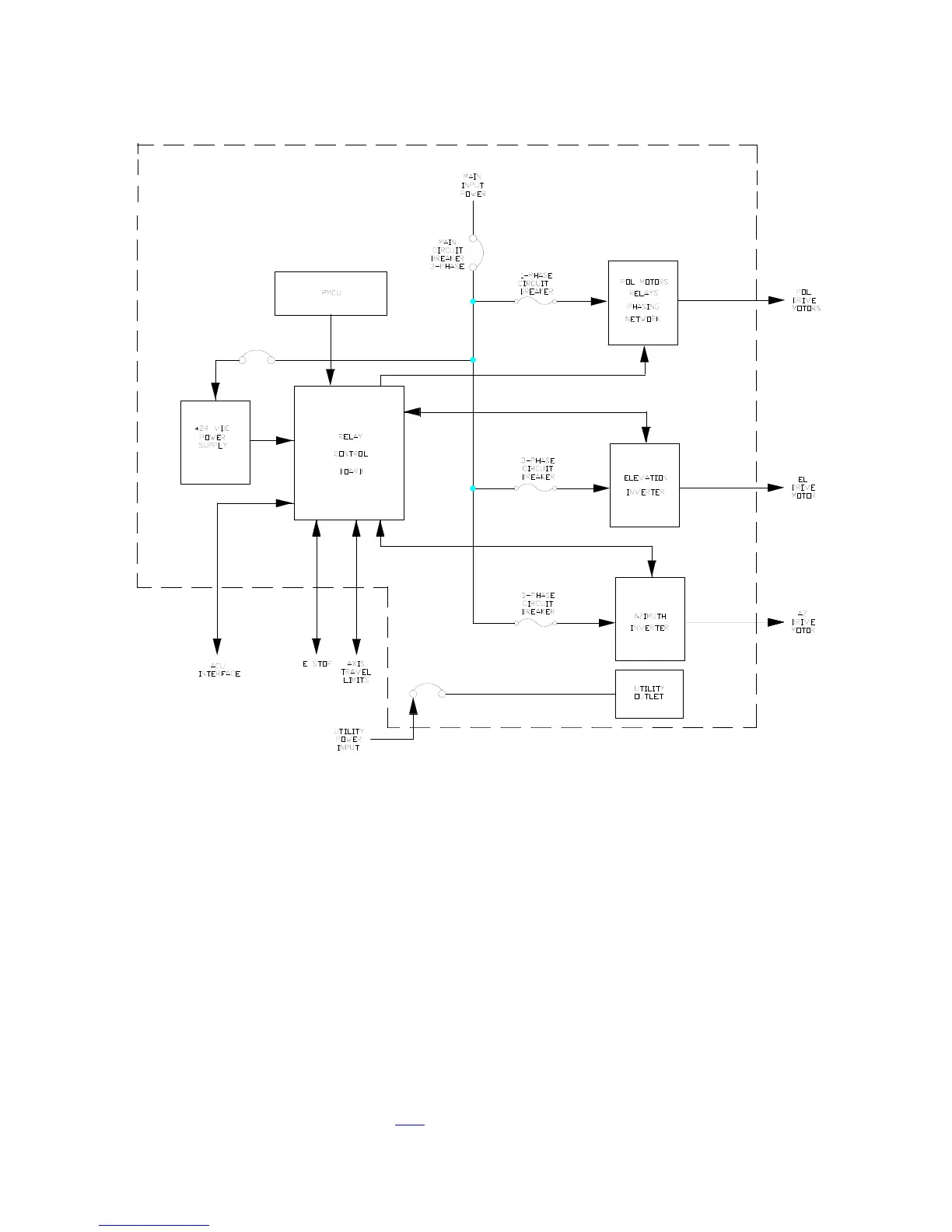
A functional block diagram of the drive cabinet is shown in Figure 2-7.
Figure 2-7 Drive Cabinet Block Diagram
The drive cabinet consists of the following major components:
• Portable Maintenance Control Unit
• Main and Inverter Drive Circuit Breakers
• EMERGENCY STOP SWITCH
• AZ Variable Speed AC Drive Unit (Inverter)
• EL Variable Speed AC Drive Unit (Inverter)
• 24 VDC Power Supply
• Control Circuitry for the POL Motors (In Three-Axis and Four-Axis Systems)
Figure 2-8 shows the major components of the drive cabinet. Refer to the
engineering drawings in Section 7.0.
2-17