Installation
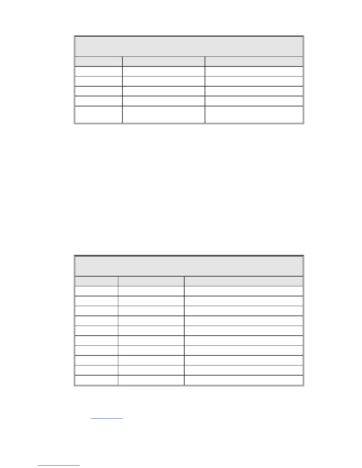
TABLE 4-12 STANDARD COMMUNICATION PORT
CONNECTIONS (EIA/TIA-232E)
J14, J15 DESIGNATION FUNCTION
1 PROT GND Protective Gnd
2 EIA/TIA-232 XDATA Transmit
3 EIA/TIA-232 RDATA Receive
7 SIG GND Signal Gnd
9 * (see below) +12V (off by default)
Fiber Optic Modem Power
(Enabled by SW1 on rear panel)
A RS-232 cable run longer than approximately 50 feet requires fiber optic cables
with a fiber optic modem at each end. The modem can be powered by +12V
supplied by pin 9 of each RS-232 port (J14 and J15). Each connector is
individually switched by a DIP switch, SW1 Modem Power, located on the rear
panel (see Figure 4-4). The top switch controls J14, and the bottom switch
controls J15. Both switches are in the left position (off) by default.
General Dynamics offers the following fiber optic modems (optional):
BFM001 - 25 pin D (powered by pin 9)
BFM002 - 25 pin D (externally powered)
BFM020 - External Power source for BFM002
TABLE 4-13 COMMUNICATION PORT CONNECTIONS (EIA/TIA-
422B)
J16, J17 DESIGNATION FUNCTION
1 GND Ground
2
6 XDATA- Transmit (-) *
9 RDATA- Receive (-) *
15
16
19 XDATA+ Transmit (+) *
20 XDATA SHLD Transmit Shield *
22 RDATA+ Receive (+) *
23 RDATA SHLD Receive Shield *
* Standard connection scheme for EIA/TIA-422B port.
NOTE: If a PMCU with Position Display is connected as specified in
Section 4.3.4.3.2, J16 is not available for use with an M&C system.
4-19