Installation
NOTE: The table below only applies to 800499-02.
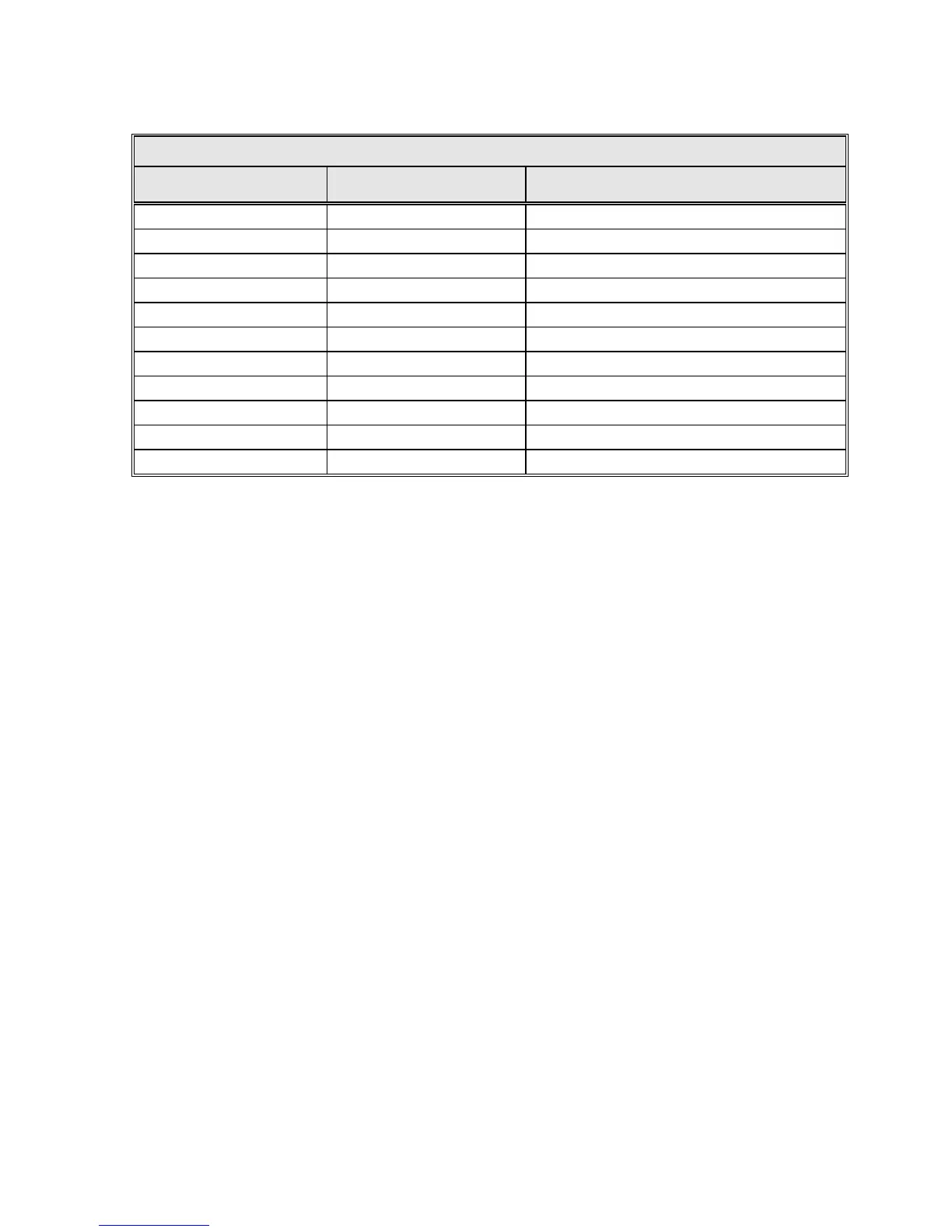
TABLE 4-9 POSITION DISPLAY UNIT TABLE
PDU – J1, J2 FUNCTION
AZIMUTH & ELEVATION OPTICAL ENCODER
J-BOXES J3
15 CLK 1
16 CLKN 2
17 SHLD (CLK) NC
18 CLK2 7
19 CLK2N 8
20 SHLD (CLK2) 10
21 DAT 3
22 DATN 4
23 SHLD (DAT) 9
24 +24V 5
25 24V RTN 6
4.3.6 Analog Input Connections
One analog input port is provided on the 7200 ACU via J21 on the rear panel (refer
to Figure 4-4). Internally, the analog input connects to an A/D converter circuit that
provides tracking signal inputs to the main processor.
The analog input has (+), (-), and GND terminals to facilitate devices with isolated
or differential outputs. In most cases, the (+) output of the tracking receiver
connects to the (+) analog input, and the common or (-) output of the tracking
receiver connects to the (-) analog input with no further connections required. The
analog input voltage range is 0 to 10 VDC. The voltage per dB slope range is 0.1
to 1.0 V/dB.
NOTE: When connecting a General Dynamics TRL or DTR Tracking
Receiver via serial link, the analog input is not used. However, when
connecting a Model 253 Tracking Receiver via serial link, the analog input is
required to return the signal level back to the 7200.
Refer to Table 4-10 and connect the analog input to J21 (9-pin D-connector) on
the rear panel of the 7200 ACU.
4-16