SITE TEST PROCEDURE
F - 13
1.8.2 Tracking Accuracy
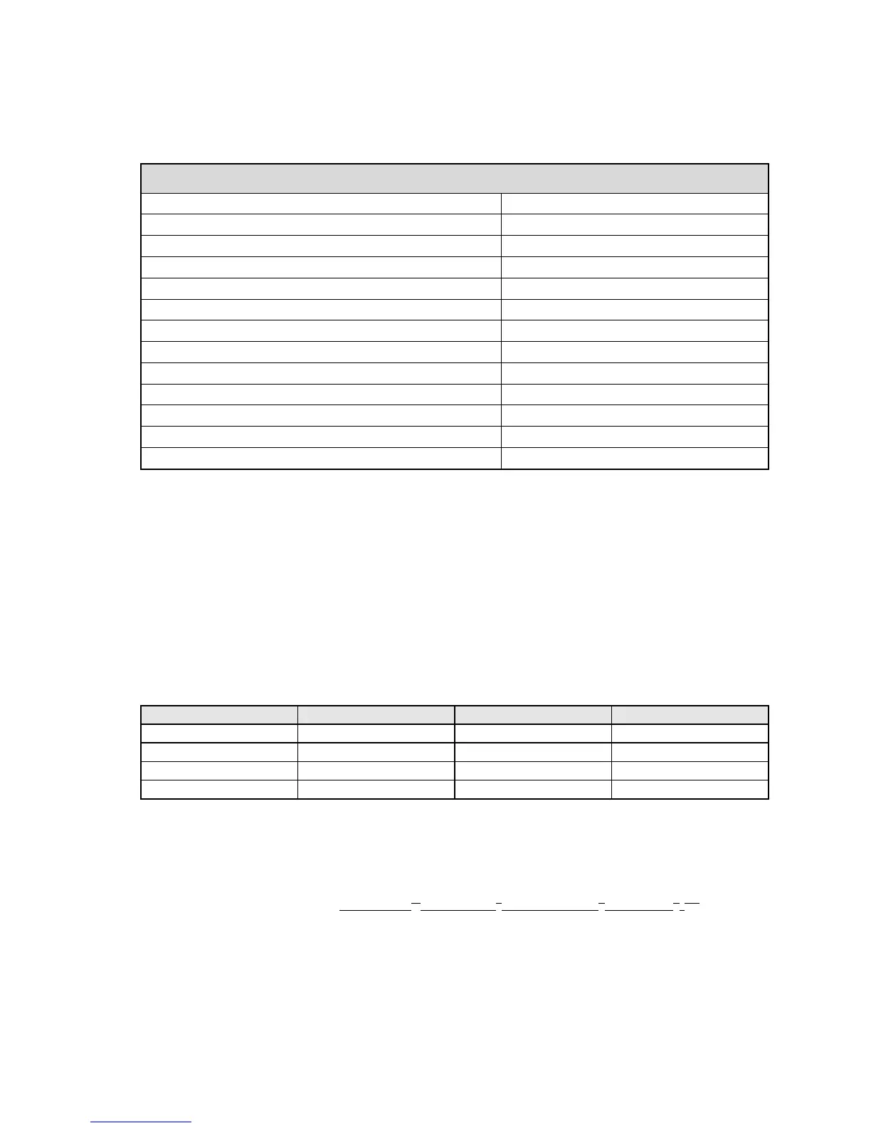
Record Steptrack Defaults Parameters in the following table.
STEPTRACK DEFAULTS
Cycle time (hh:mm:ss)
Receive -3dB beamwidth (deg)
Step size (deg)
Position deadband (deg)
Maximum no. of cycles
Cycle to start rate estimates
Peaking correction limit (%BW)
Weight adjustment value (0-1)
Low tracking signal level (dB)
Signal threshold (dB)
Axis to peak first (AZ,EL)
# of samples
Sun outage protection (enabled,disabled)
1. In Manual antenna control, move the antenna off beam center in the direction
listed in the following table until the signal level drops 2dB.
2. Activate Steptrack and allow the system to repeak the antenna and record the
resulting signal level from the 7200 ACU display below in the TRACK LEVEL
column.
3. Return to Manual antenna control and manually peak the antenna and record
the resulting signal level in the MANUAL LEVEL column. Repeat steps 1-3 for
each subsequent direction listed in the following table.
DIRECTION TRACK LEVEL MANUAL LEVEL ERROR
AZ CCW
AZ CW
EL UP
EL DOWN
NOTE: If the level achieved in Steptrack is greater than that achieved in
manual peaking, enter a zero for the error.
4. Calculate the RMS tracking accuracy as follows:
RMS TRACKING ERROR = [(AZCCW)
2
+ (AZCW)
2
+ (ELDOWN)
2
+ (ELUP)
2
]
1/2
2
5. Record the RMS TRACKING ERROR (< 0.1 dB, Nominal) _____dB(Record)