Operation
5.8.5.11.2 Serial 253 Diagnostics
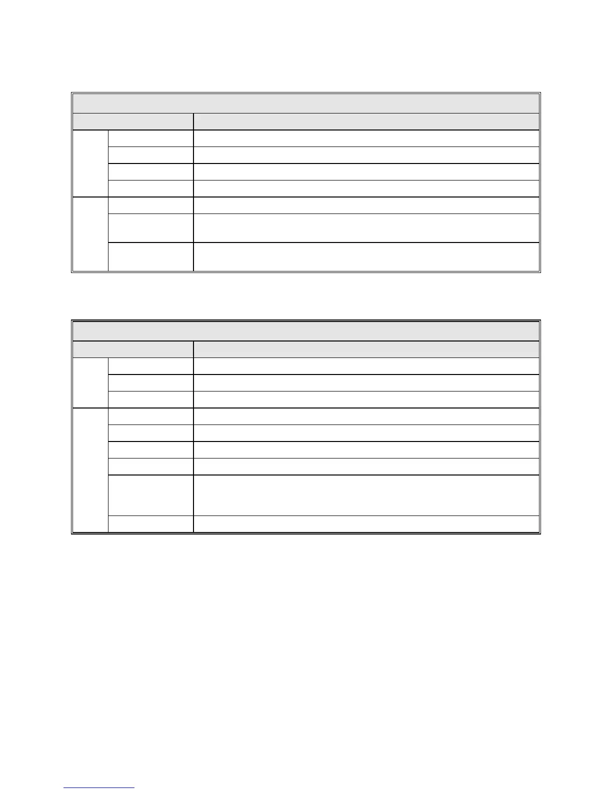
TABLE 5-24 SERIAL 253 DIAGNOSTIC FIELDS
FIELD DESCRIPTION
Link
# good reads # of successful transactions with the 253.
# aborts # of bad/partial responses from receiver
# cksum fail # of incorrect checksums in packets from receiver
# timeouts # of timeouts with 253 ( no response from receiver)
Data
Frequency Value returned from the 253 receiver in kHz
Bandwidth
Selected IF returned from 253 receiver [1-
3], refer to documentation for RF
Board for specific filter values used
Status bytes
Read status bits right to left where furthest right is bit 0 See "Request System
Status" in 253 Tracking Receiver Software Interface for detailed description.
5.8.5.11.3 Serial TRL Diagnostics
TABLE 5-25 SERIAL TRL DIAGNOSTIC FIELDS
FIELD DESCRIPTION
Link
# ok Number of successful transactions with the TRL.
# aborted Number of aborted transactions with the TRL.
# timeouts Number of timeouts with TRL (# aborted may also increment).
Data
Beacon Beacon currently selected on TRL. [0-16]
TRL port TRL serial port ACU is connected to. [1-2]
Control TRL control point. ["Local", "Serial 1|2", "Parallel"]
Attenuation Attenuation value in dB*10. [0-500]
Errors
Bit mapped hex: [00h-3Fh] b0=out of band; b1=AIB failure; b2=1st LO
failure; b3=2nd LO failure; b4=PLL/AFC failure; b5=beacon error; b6-
b7=unused.
Voltage Value in VDC*1000. [0-9999]
5.8.5.12 Power-up Test Report
The Power-up test report option provides the time that the ACU was last powered
up, and any unlikely problems with the I/O cards. If any errors were detected on
these cards at power-up, errors will be displayed. This screen can occasionally be
useful for debugging.
5-48