EasyManuals Logo

General Dynamics 7200 User Manual

General Dynamics 7200
252 pages
To Next Page IconTo Next Page
To Previous Page IconTo Previous Page
Page #65 background imageLoading...
Page #65 background image
Installation
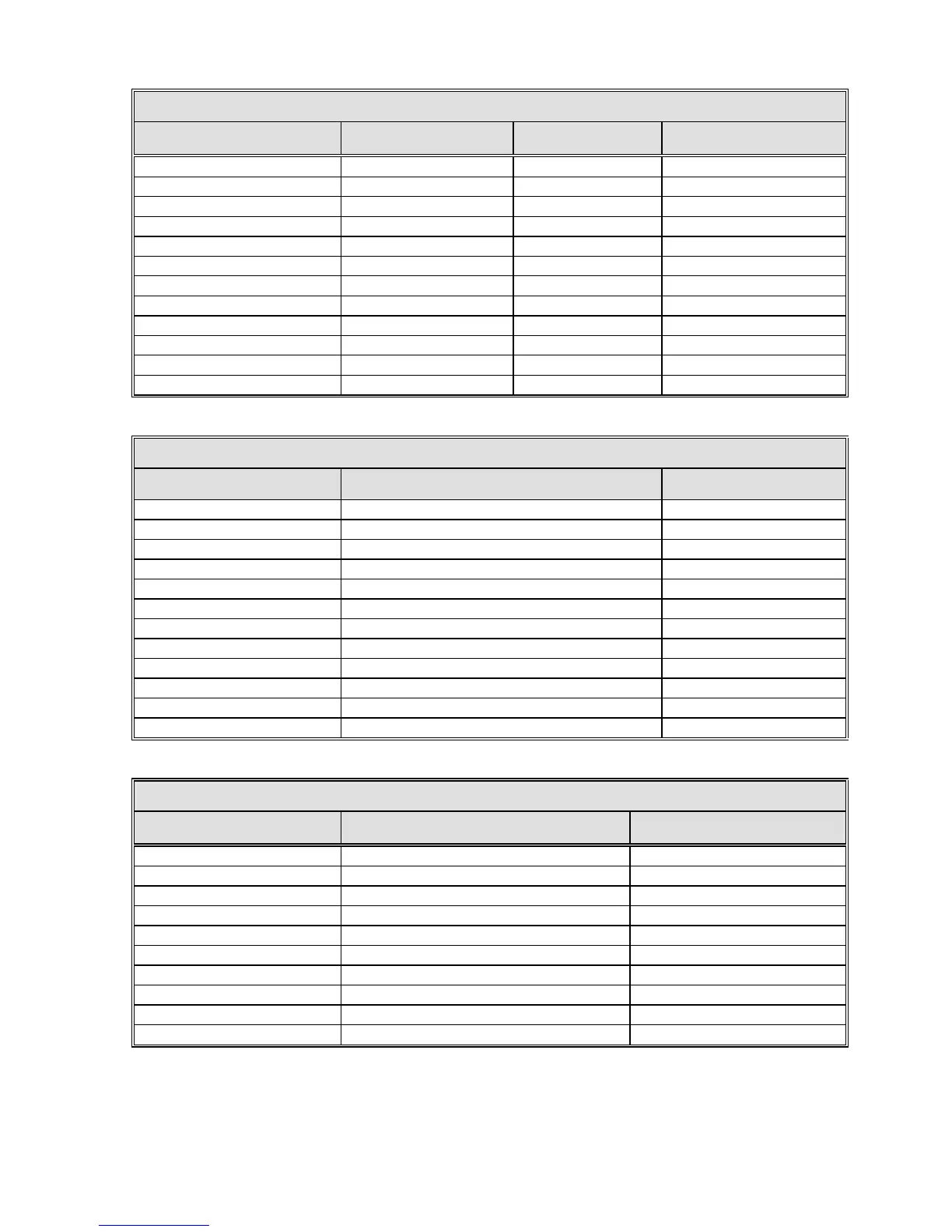
TABLE 4-8A 17/19-BIT OPTICAL ENCODER CONNECTIONS TABLE
OPTICAL ENCODER COLOR FUNCTION 800499-02 800499-01
PUR
CLK
1
1
YEL
CLKN
2
2
GRY
DAT
3
3
PNK
DATN
4
4
BRN/GRN
+5V
7
7
BLU +5V 7 7
WHT/GRN
GND
8
8
WHT
GND
8
8
BRN
N/A
9
5
GRN
N/A
10
6
RED
N/A
11
9
BLK
N/A
12
10
TABLE 4-8B 26-BIT OPTICAL ENCODER CONNECTIONS TABLE
OPTICAL ENCODER COLOR FUNCTION 800499-01
PUR
CLK
1
YEL
CLKN
2
GRY
DAT
3
PNK
DATN
4
BRN/GRN
+5V
7
BLU
+5V
7
WHT/GRN
GND
8
WHT
GND
8
GRN/BLK
N/A
5
YEL/BLK
N/A
6
BLU/BLK
N/A
9
RED/BLK
N/A
10
TABLE 4-8C 18-BIT OPTICAL ENCODER CONNECTIONS TABLE
OPTICAL ENCODER COLOR FUNCTION 7200 PIN OUT
YELLOW
CLK
15
GREEN
CLKN
16
PINK DAT 21
GRAY
DATN
22
WHITE (Large)
+24V
24
BROWN (Large)
0V
25
BLK
N/A
N/A
VIOLET
N/A
N/A
BLUE
N/A
N/A
RED
N/A
N/A
Note: Shield must be terminated on pins 17 & 23 for CLK and DATA respectively
on the 7200 side for noise reduction purposes.
4-15

Table of Contents

Questions and Answers:

Question and Answer IconNeed help?

Do you have a question about the General Dynamics 7200 and is the answer not in the manual?

General Dynamics 7200 Specifications

General IconGeneral
BrandGeneral Dynamics
Model7200
CategoryControl Systems
LanguageEnglish