SITE TEST PROCEDURE
F - 3
1.0 SITE ACCEPTANCE TEST PROCEDURE
1.1 Preliminary Information
This test procedure is intended to serve as the final proof of performance
document for the 7200 ACS, subsequent to field installation and set-up. Prior to
the performance of these tests, the system must have been installed and adjusted
as described in Section 4.0 of this manual. All motor rotation directions should be
normalized, all limit stops should be set, and the Radio Frequency (RF) equipment
used to provide the analog tracking signal should be calibrated for proper system
performance.
This procedure is provided for both two, three-axis and four-axis systems. Ignore
all references to the POL axis drive components for two-axis systems. The 3-axis
system has POL and the four-axis has POL & 4th Axis.
1.2 Drive Cabinet Line Voltage Measurements and Power-Up
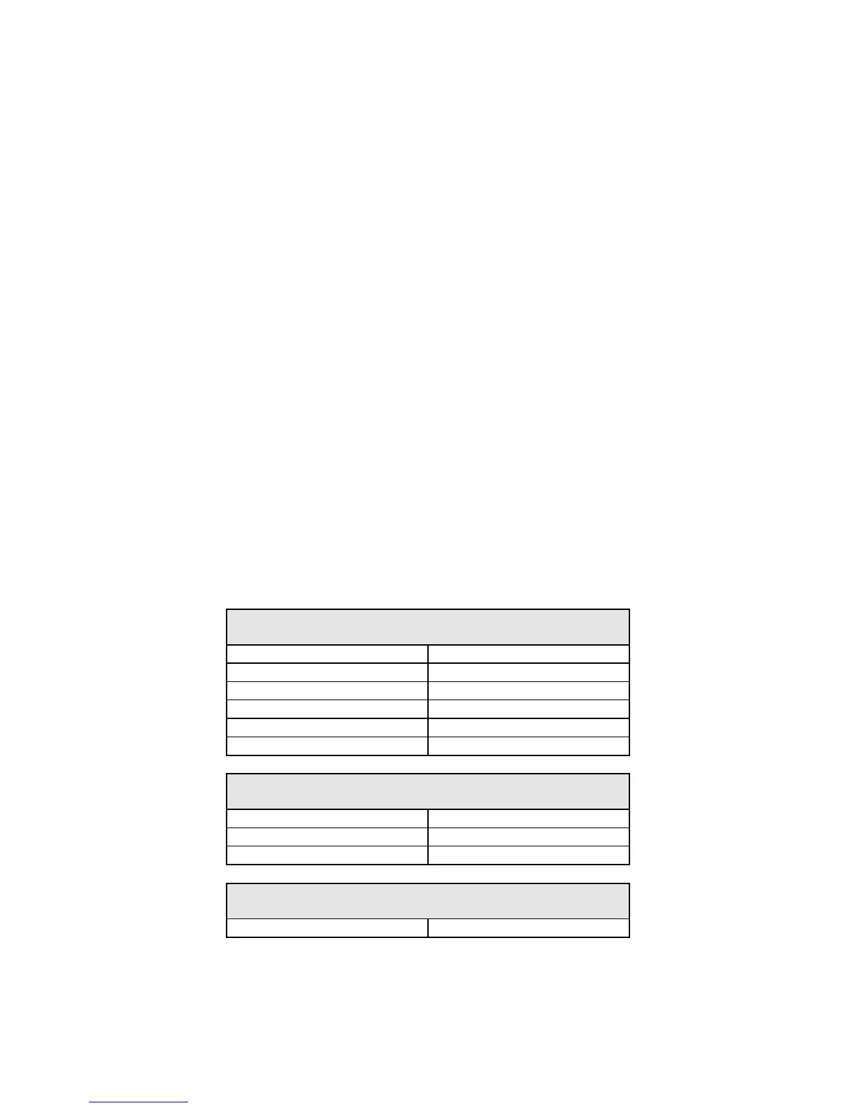
1. Using an AC voltmeter with the main circuit breaker OFF, measure and record
the voltages on the line (upper) side of the main breaker as indicated below
(record data under the appropriate heading for the main power provided for
this system):
3-PHASE SYSTEMS
(4-WIRE + GROUND)
A phase to B phase VAC
B phase to C phase
VAC
C phase to A phase VAC
A phase to Neutral VAC
B phase to Neutral VAC
C phase to Neutral VAC
SINGLE-PHASE SYSTEMS
(3-WIRE 2-WIRE + GROUND)
L1 to L2 VAC
L1 to Neutral VAC
L2 to Neutral VAC
SINGLE-PHASE SYSTEMS
(2-WIRE + GROUND)
Line to Neutral VAC