Operation
5.8.5.1.5 RDC States
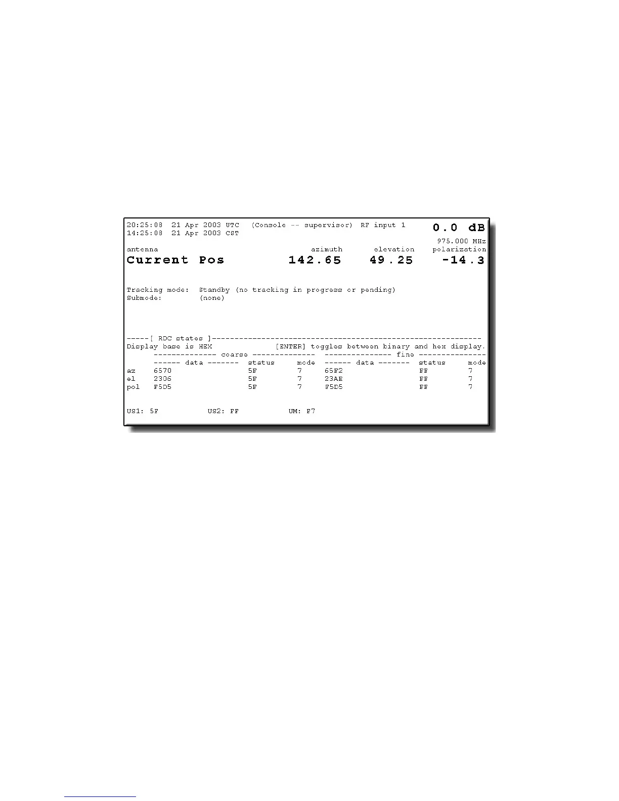
The information shown in Figure 5-11 shows the state of the RDC card. This data
is primarily used for debugging systems with standard resolvers. On single-speed
systems, AZ and EL fine data, states, and mode will show all bits as F
(hexadecimal).
The information is displayed in hexadecimal by default, but can be changed to
binary display by pressing [ENTER] to toggle between hexadecimal and binary.
Figure 5-11 RDC States Display
On systems with two-speed resolvers, this information is also used to determine
the internal alignment of the resolver (i.e., the fine resolver value when the coarse
resolver value is 0). Even though it is unused on two-speed resolver systems, POL
fine bits will always show all bits as 1's. On systems without two-speed resolvers,
the fine data fields should show FFFF in hexadecimal (or 1111 1111 1111 1111 in
binary).
US1 and US2 are unused states 1 and 2, and UM is unused mode, but all should
show 1's. The status and mode information are not useful to the user; they are
provided for General Dynamics engineers' use only and are not documented here.
5.8.5.1.6 VCPU Hardware Diagnostics
This diagnostic is fully functional even in simulation mode. The CPU board
temperature is displayed at the top of the window. Fault status indicators are
shown in [brackets] when that fault is clear, and in reverse video when that fault is
sensed. Raw status is shown at the bottom, for use by technical support. This is
done only for a sanity check; all the data encoded there is displayed above in
human-readable format. The functions are outlined below.
5-39