Overview
Potentiometer PT4 – The analog input circuit contains a zero offset calibration
potentiometer PT4. Refer to the A/D Calibration section of General Dynamics
Document #CG-0283.
Potentiometer PT5 – The analog input circuit contains a gain calibration
potentiometer PT5. Refer to the A/D Calibration section of General Dynamics
Document #CG-0283.
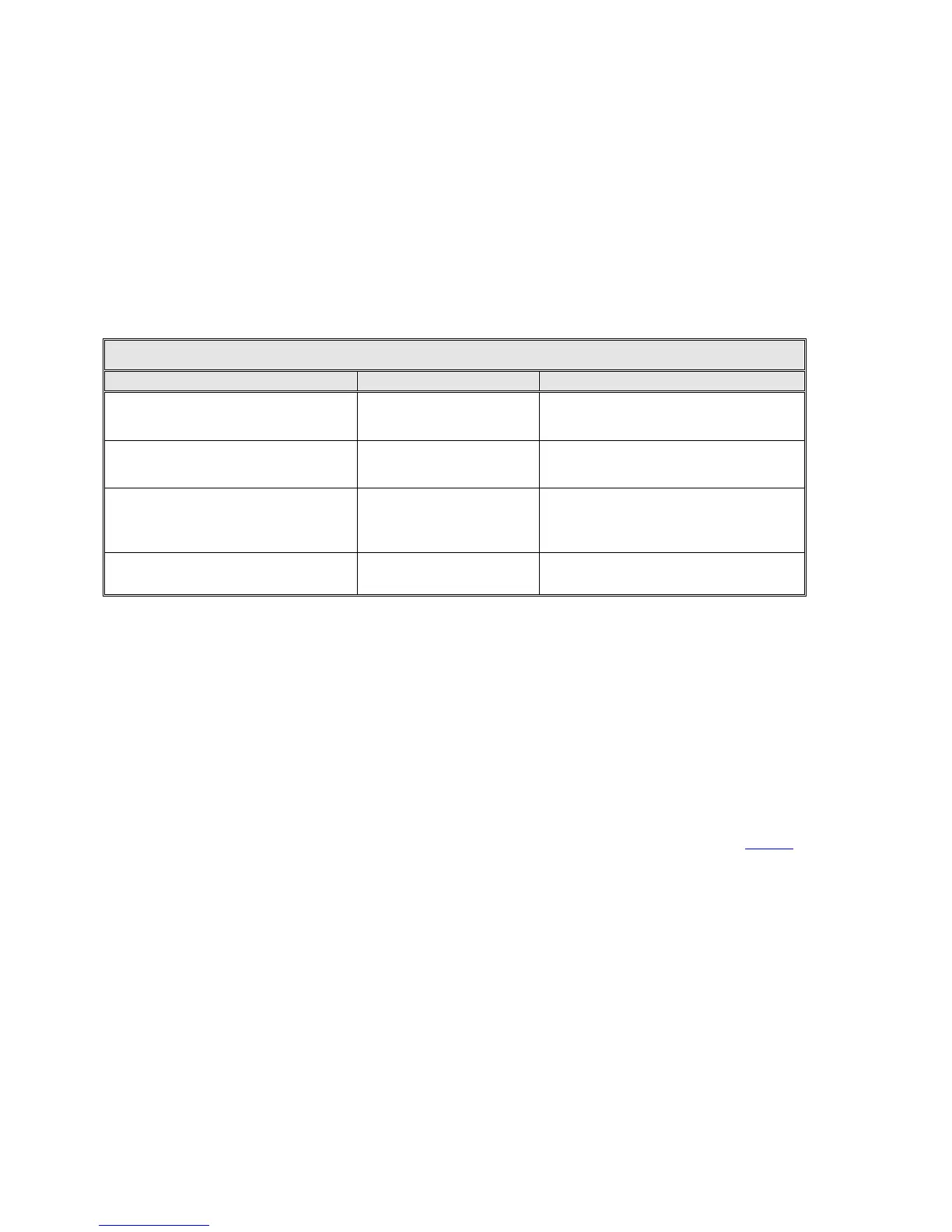
Table 2-6 provides miscellaneous performance specifications that are inherent to
the VCPU board.
TABLE 2-6 VCPU PERFORMANCE SPECIFICATIONS
Real Time Clock Accuracy
(A TCXO drives this clock)
+/- 0.16 Seconds/Day
+0.26 to –0.42 Seconds/Day
(@ 0-50 Degrees C)
NVRAM Battery Backup Shelf Life
(external power source off)
24 Months
15 Months
(@ 0 Degrees C)
NVRAM Battery Backup
Normal Operation (external power
source operational)
-
90% capacity after 10 years due to
self discharge
(@ 25 Degrees C)
Battery Change Period (without
NVRAM corruption) *
>45 Seconds >21 Seconds
* A capacitor keeps the NVRAM powered while the battery is being replaced. This row in the table defines the minimum
amount of time that the discharging capacitor will keep the NVRAM powered without the battery present.
2.4.1.2 User Interface
One of the most striking and advanced features of the 7200 ACU is the user
interface, which combines an 8-inch by 4-inch electroluminescent display with a
custom 24-station keypad to provide the most straightforward, powerful, and user-
friendly operating platform in the industry. As shown in Figure 2-2, the 7200 ACU
front panel layout is uncluttered and offers a logical format for the display of
information. For more information on the user interface refer to Section 2.5.1.
2.4.1.3 Digital Input/Output Printed-Circuit Board Assembly
The I/O PCB provides the electrical interface between the ACU and the drive
cabinet. In addition, the I/O card serves as the interface between the CPU and the
ACU rear panel status inputs and control outputs. There are a total of 24 digital
inputs (some inputs are used internally so all 24 are not available through the rear
panel connectors). See table 2-7 for the digital inputs specifications.
2-13