Installation
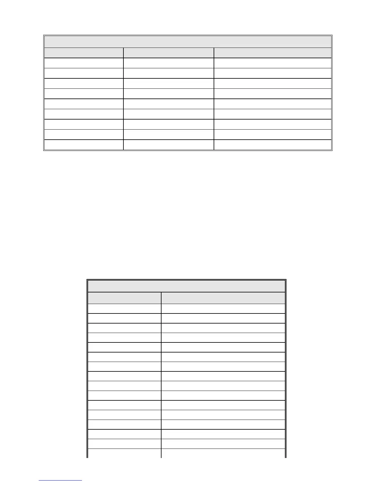
TABLE 4-10 ANALOG INPUT CONNECTIONS
J21 DESIGNATION FUNCTION
1 GND Chassis Ground
2 AD1+ Channel 1(+) *
3 AD1 GND Chassis Ground
4 NOT USED No Connection
5 NOT USED No Connection
6 GND Chassis Ground
7 AD1- Channel 1(-) *
8 NOT USED No Connection
9 NOT USED No Connection
* Standard connection scheme.
4.3.6.1 A/D Circuit Calibration
A calibration procedure is performed at the factory as part of the normal product
configuration, therefore a field calibration is only performed if operational problems
due to drift are encountered at a later date or if different video receivers are used
in the AGC mode. Should field calibration be necessary, refer to General Dynamics
Document #CG-0283
4.3.7 Digital Inputs
The input pairs for the Digital Input, J11, are shown in Table 4-11.
TABLE 4-11 DIGITAL INPUTS – J11
7200 ACU – J11 INPUTS
1 24 -
2
24+
3
23 -
4 23 +
5
22 –
6 22 +
7 21 -
8 21 +
9 20 -
10 20 +
11 19 -
12 19 +
13 18 -
14 18 +
15 17 -
16 17 +
4-17