Operation
5.8.5.11 Serial Diagnostics Menus
One of the following menus will appear in the Display System Status menu if that
respective type of tracking receiver is selected in the Shell parameter under
Remote port configuration...
• Serial DTR Diagnostics
• Serial 253 Diagnostics
• Serial TRL Diagnostics
The screens show "raw" status values being transmitted by the respective tracking
receiver to the ACU. It is normally only of interest to General Dynamics engineers
troubleshooting the serial link. While this screen is still available for viewing in
simulation mode, the respective tracking receiver interface is not active, and the
selected tracking receiver is not being queried or commanded while in simulation
mode. The Link fields show values since power-up or last reset. [ENTER] resets
the link counters to 0. Details for each type of receiver can be seen in Tables 5-
23, 5-24 and 5-25.
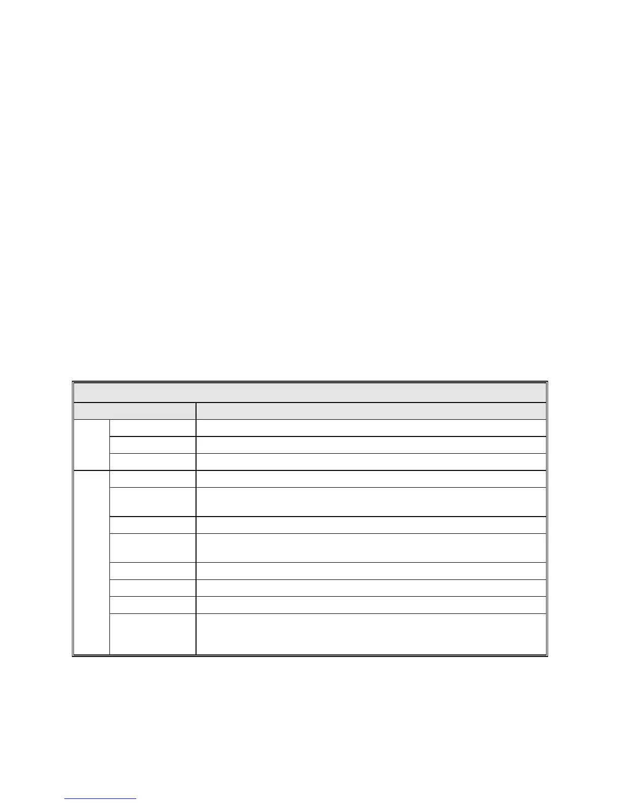
5.8.5.11.1 Serial DTR Diagnostics
TABLE 5-23 SERIAL DTR DIAGNOSTIC FIELDS
FIELD DESCRIPTION
Link
# ok Number of successful transactions with the DTR.
# aborted Number of aborted transactions with the DTR.
# timeouts Number of timeouts with DTR (# aborted may also increment).
Data
Power Received signal power in dBm
Frequency
DTR's currently selected frequency. If the ACU is in remote c
DTR, this should match the value on the real-time display.
DTR port Which serial port on the DTR the ACU is connected to.
Control
Which serial port on the DTR is currently in control of the DTR. Control = 5
indicates DTR is in local control.
Pol select Which pol input is in use on the DTR [1-2].
FFT sample avg FFT sample averaging [1-2000]
Filter BW (Bandpass) Filter bandwidth [0-3] ([0-11] with wideband DTR option)
Detection type
-1 indicates this is not a wideband DTR, so this is not user-
selectable (which
means FFT signal is in effect.) 0=FFT signal; 1=FFT noise; 2=RMS power;
3=RMS density.
5-47