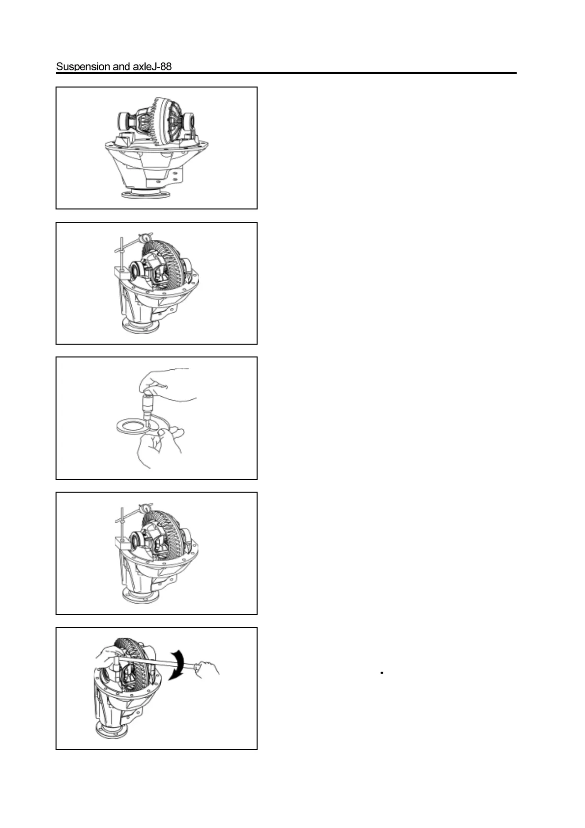
13. Place an adjusting shim in the position of front
reducer housing side bearing and close to exterior.
14. Install the other adjusting shim and the bearing
outer race of another side with the differential
assembly into the front reducer housing.
Remarks: Ensure the selected adjusting shim has
not gap with front reducer housing.
15. Rotate the driven bevel gear to make the differ-
ential assembly closed to the front reducer housing.
16. Use the dial indicator to measure the tooth side
gap between the drive and driven bevel gear.
The rational range of gap is: 0.15-0.25mm.
If the measured gap is beyond the range, then adjust it by
adding or reducing the thickness of shim. ( When add in
one side, the other side should be reduced with same
thickness)
Caution: Ensure the selected adjusting shim is
without clearance form front reducer housing.
17. Adjust the pre-applled axial load of side bearing.
a. Remove two adjusting shim, remeasure the thickness of two
adjusting shims.
b. Install the new adjusting shim with thickness 0.06-0.09mm
more than that of removed adjusting shim, then install it with
the differential in the reducer housing.
c. Remeasure the tooth side clearance between the drive bevel
gear and driven bevel gear.
Rational range of clearance: 0.15-0.25mm
Remarks: If the measured gap is beyond the range, then adjust
it by adding or reducing the thickness of shim. ( When add in
one side, the other side should be reduced with same
thickness)
Caution: Ensure the selected adjusting shim has not the
clearance with the front reducer housing.
18. Install the bearing gland of both sides and use
the wrench to tighten it to the specified torque.
specified torque : 90-115N m
Remarks: Distinguish the left and right during assembly.