electric clutch detector
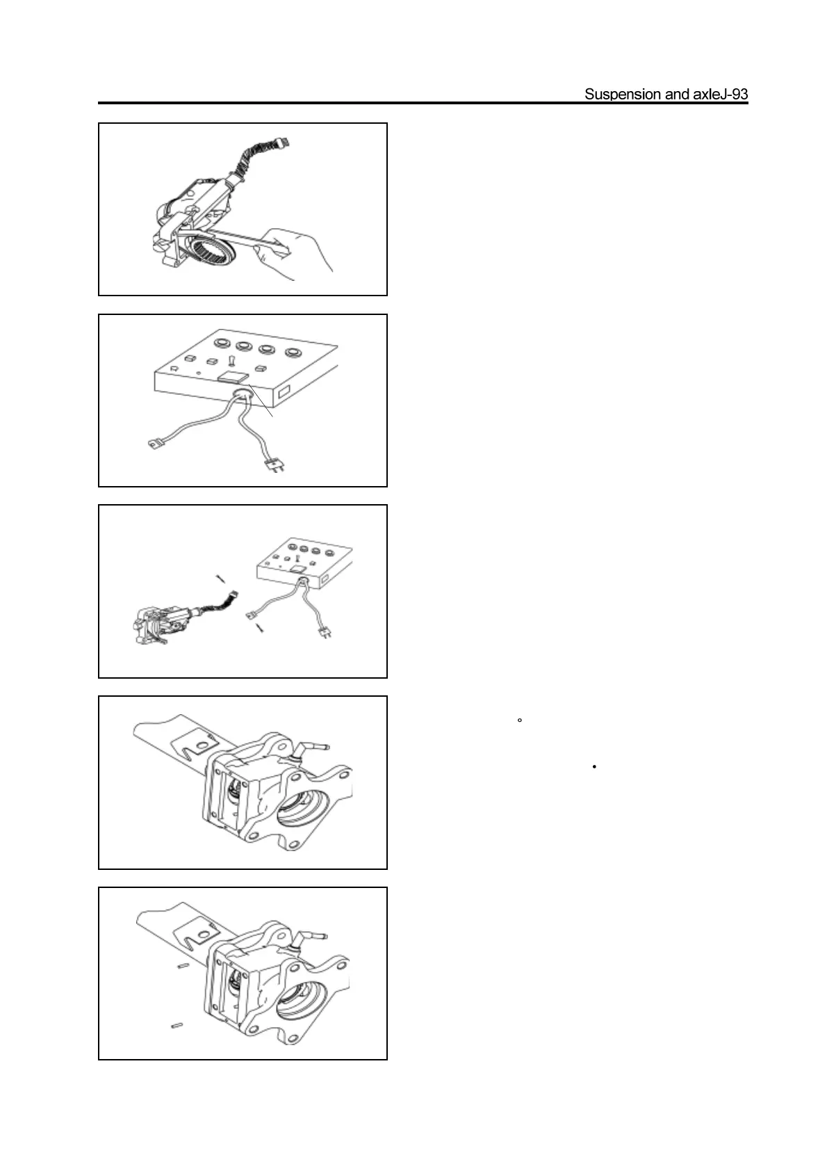
37. Detect the electric clutch assembly .
a. Measure the clearance between the shift fork and shift fork
sleeve.
Range of clearance : 0.2-0.4mm
It should replace the electric clutch assembly and shift fork
sleeve when the clearance is not in the range.
b. Connect the electric clutch assembly to the electric clutch
detector and power the electric clutch detector with 220V
power supply to test the electric clutch (Before the test,
adjustthe test controller status to make the motor starting time
is 3s ,the time form found the actuator is not in position to
restartingis 2.5s and the time of controller to redrive the
electric clutch is2s) The motor starts for 3s when the gear
switch is shifted form 2WD to 4WD, the lamp flashes at the
same time, the clutch is in 4WD status, the indicator lamp is
light always. If does not reach the 4WD status in the first
time, then the controller restarts it for 2s after 2.5s delay, the
lamp flashes at the same time; if it is still not in position, then
the indicator lamp flashes twice continuously, the indicator
lamp is extinguished for 1s, the motor is stopped. That means
the electric clutch is unqualified and should be replaced by the
qualified product. The motor starts for 3s normally when the
clutch is shifted form 4WD to 2WD, the lamp flashes at the
same time, when the clutch is in 2WD status, the indicator
lamp is extinguished always. If does not reach the 2WD status
in the first time, then the controller restarts it for 2s after 2.5s
delay, the lamp flashes at the same time; if it is still not in
2WD status, then the indicator lamp flashes twice
continuously, the indicator lamp is extinguished for 1s, the
motor is stopped.
That means the electric clutch is unqualified and should be
replaced by the qualified product.
38. Cover the shift fork sleeve on the major
semiaxle spline.
39. Install the separator housing on the front axle
tube flange and use the bolt to tighten it to the
specified torque
(The bolt should be precoated
with the screw lock agent and the amount should be
just can cover the complete screw)
specified torque : 90-110N m
Caution: Before installation, remove the foreign material on
two matching surfaces of separator housing and front axle
tube flange; and precoat the 1596 silicon rubber plane sealant
on the front axle tube flange. Caution: Prevent the sealant
from entering into the screw hole.
40. Press in the plastic vent tube on the electric
clutch housing and front axle tube.
41. Install two location pins in the location pin hole
of electric clutch housing respectively.
42. Coat the connecting surface of electric clutch
housing and electric clutch with 1596 silicon rubber
sealant uniformly; level it by plate.
Caution: The connecting surface should be cleaned
and must not have the oil and other foreign
matters. The sealant must not enter into the elec-
tric clutch housing and screw hole.