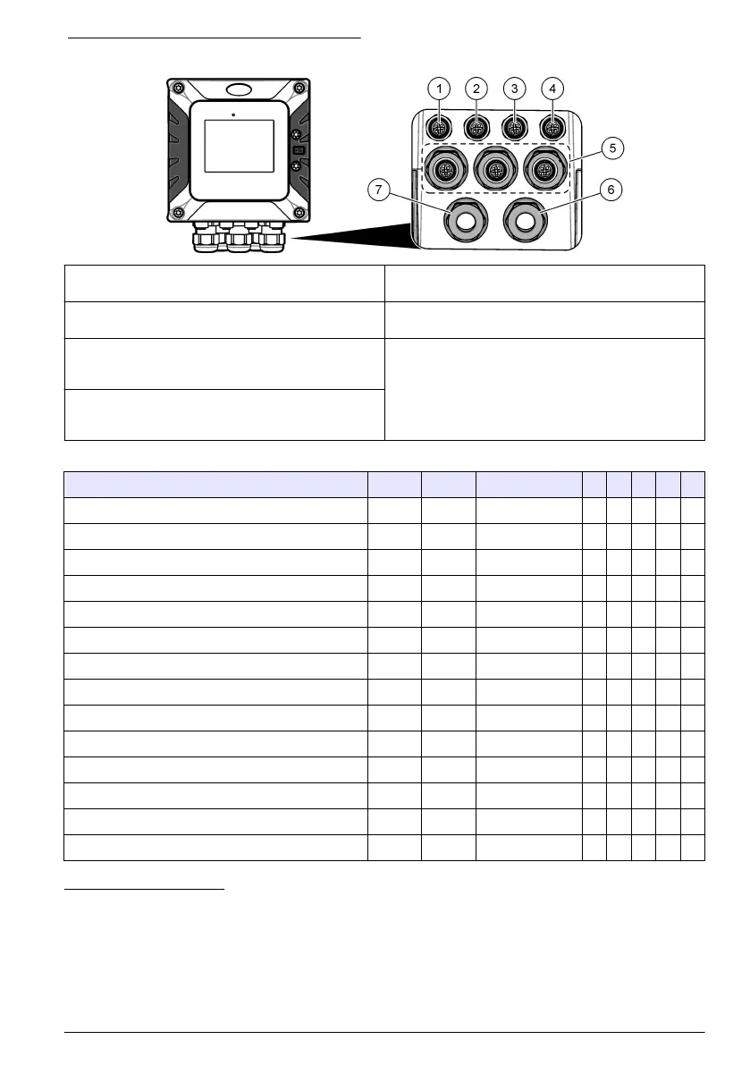
Figure 6 Electrical connectors and fittings
1 Ethernet connector (optional) for LAN port 1 or
EtherNet/IP or PROFINET connector
5 Strain relief fitting for USB box and expansion
modules: Analog inputs/outputs, Profibus DP
2 Ethernet connector (optional) for LAN port 2 or
EtherNet/IP or PROFINET connector
6 Power cord (or conduit hub)
9
3 Digital SC connector: Channel 1. Optional: Analog
sensor connection to sensor module or analog input
connection to 4-20 mA input module
8
7 Strain relief fitting for high voltage relay
4 Digital SC connector: Channel 2. Optional: Analog
sensor connection to sensor module or analog input
connection to 4-20 mA input module
Table 1 Options for each connector and fitting
Device 1
10
2 Option
11
3 4 5 6 7
sc digital sensor, sc digital gateway or analyzer X X
Analog sensor X X
4-20 mA input X X
4-40 mA output X
Profibus DP module X
USB Box X
LAN + LAN Green Green Split / Chaining
LAN + Modbus TCP Green Green Split / Chaining
EtherNet/IP Yellow Yellow IEP only
LAN + EtherNet/IP Green Yellow Mix IEP
PROFINET Yellow Yellow IEP only
LAN + PROFINET Green Yellow Mix IEP
High voltage relay X
Power supply X
8
To connect an analog sensor or 4-20 mA input to the controller, install the applicable expansion
module, if not already installed. Refer to the documentation supplied with the expansion module
for additional information.
9
The power cord is factory-installed based on the controller configuration.
10
A color code identifies the connectors. The LAN connectors are green. The EtherNet/IP or
PROFINET connectors are yellow.
11
Refer to the expanded user manual on the manufacturer's website for additional information.
English 13

 Loading...


