WinMax Lathe Conversational Part Programming v546CO Conversational Part Programming 2-87
• Z CENTER—defines the Z location of the blend arc’s center point. This read-
only field is carried forward from the previous segment and can only be
edited in that screen.
• C CENTER (DEG)—defines the angle of the blend arc segment center point,
measured counterclockwise from the home position. This read-only field is
carried forward from the previous segment and can only be edited in that
screen.
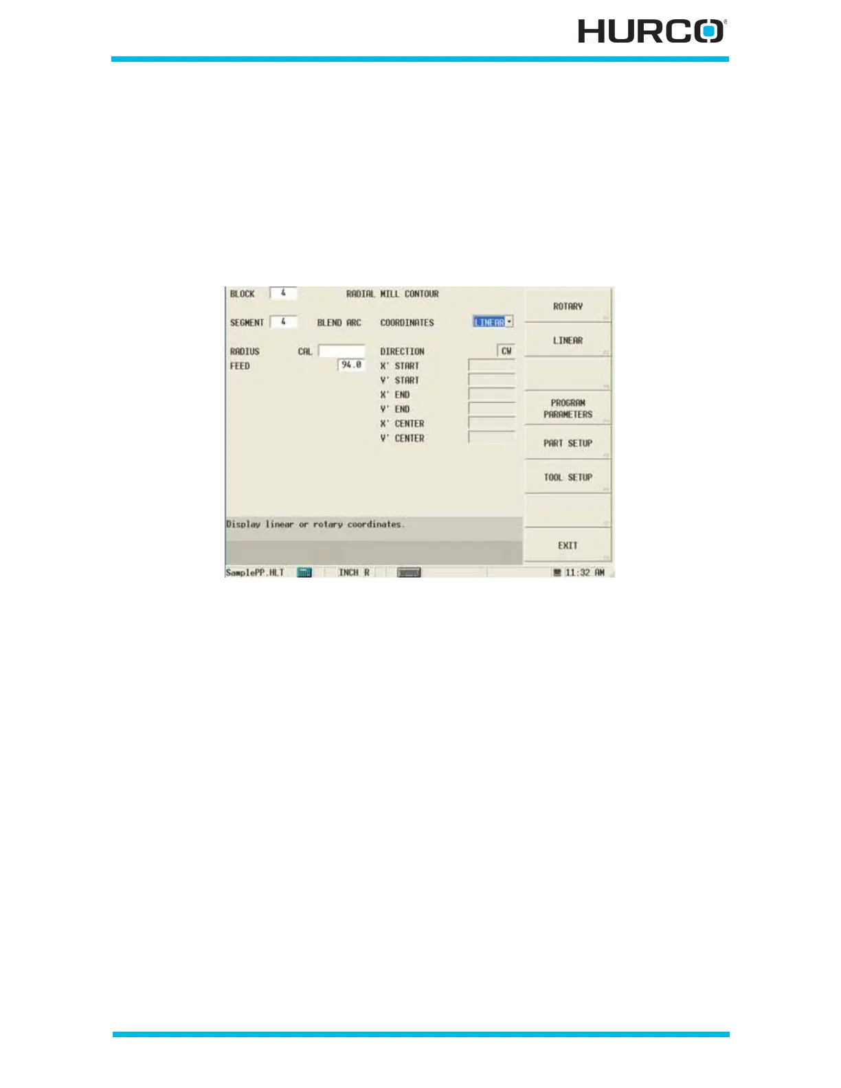
When Linear is selected in the COORDINATES field, these fields appear:
Figure 2–75. Live-Tooling Radial Mill Contour Blend Arc Segment screen: Linear Coordi-
nates
• RADIUS—defines the radius of the blend arc.
• FEED—contains the feed rate from the previous segment. This value can be
accepted or changed.
• DIRECTION—defines the direction, clockwise or counterclockwise, of the
blend arc from the start point.
• X’ START—contains the X start point for the segment. The X’ axis will move
in the physical Z direction. This read-only field is carried forward from the
previous segment and can only be edited in that screen.
• Y’ START—contains the Y start point for the segment. The Y’ axis will be
wrapped on the cylinder diameter. This read-only field is carried forward from
the previous segment and can only be edited in that screen.
• X’ END—defines the X location of the blend arc’s end point. The X’ axis will
move in the physical Z direction. This read-only field is carried forward from
the previous segment and can only be edited in that screen.
• Y’ END—defines the Y location of the blend arc’s end point. The Y’ axis will be
wrapped on the cylinder diameter. This read-only field is carried forward from
the previous segment and can only be edited in that screen.
 Loading...


