2 - 88 Conversational Part Programming v546CO WinMax Lathe Conversational Part Programming
• X’ CENTER—defines the X location of the blend arc’s center point. This read-
only field is carried forward from the previous segment and can only be
edited in that screen.
• Y’ CENTER—defines the Y location of the blend arc’s center point. The Y’ axis
will be wrapped on the cylinder diameter. This read-only field is carried
forward from the previous segment and can only be edited in that screen.
A blend arc joins two other segments and is tangent to both. A blend arc can be used to
join these types of segments:
•two Line segments.
• a Line segment and an Arc segment.
•two Arc segments.
The segments to be joined must have a theoretical point of intersection. If the only
information known about an arc is its radius, it is easier to program it as a blend arc (if
the segments intersect). The diagram below illustrates some examples of blend arcs.
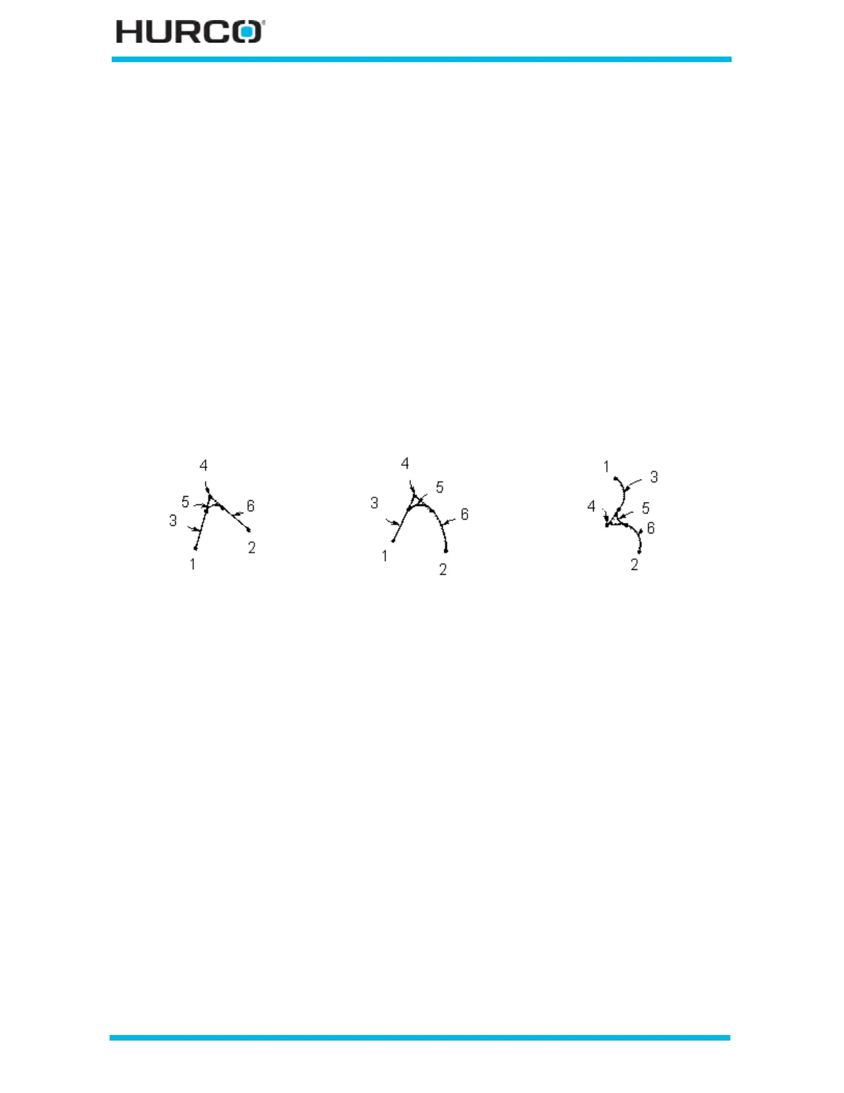
Figure 2–76. Blend Arc Examples
Some guidelines that must be followed when creating a blend arc follow:
• The first or last segment of a Radial Mill Contour data block cannot be blend
arc segments.
• Blend arc segments cannot be adjacent to one another in a program. For
example, if segment #2 is a blend arc, neither segment #1 nor #3 can be
blend arc segments.
Two Lines joined by a
Blend Arc
Line and Arc Joined by a
Blend Arc
Two Arcs Joined by a
Blend Arc
1 X/Y Start
2 X/Y End
3 Segment 1 (Line)
4 Segment 1 End/
Segment 3 Start
(Point of Intersection)
5 Segment 2 (Blend Arc)
6 Segment 3 (Line)
1 X /Y Start
2 X/Y End
3 Segment 1 (Line)
4 Segment 1 End/
Segment 3 Start
(Point of Intersection)
5 Segment 2 (Blend Arc)
6 Segment 3 (Arc)
1 X/Y Start
2 X/Y End
3 Segment 1 (Arc)
4 Segment 1 End/
Segment 3 Start
(Point of Intersection)
5 Segment 2 (Blend Arc)
6 Segment 3 (Arc)
 Loading...


