WinMax Lathe Conversational Part Programming v546CO Conversational Part Programming 2-107
• CORNER RADIUS—defines the radius of the slot end.
• X START (DIA) or (RAD)—defines the location where Plunge Feedrate
begins. The feedrate is set in the Plunge Feed field in the Process tab.
• X BOTTOM (DIA) or (RAD)—accesses selections for the bottom of the slot
and the location where the Plunge Feed Rate ends.
• AT START (DIA) or (RAD)
• AT END (DIA) or (RAD)
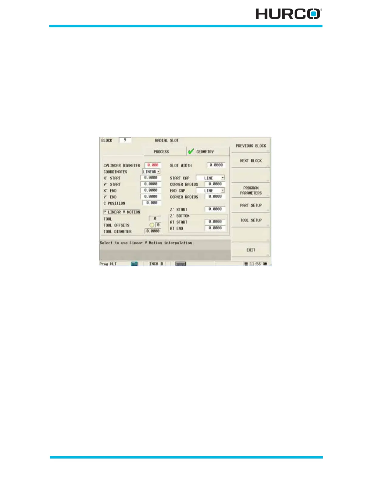
When Linear is selected in the COORDINATES field, these fields appear:
Figure 2–91. Live-Tooling Radial Mill Radial Slot screen Geometry tab: Linear Coordi-
nates
• X’ START—defines the X start point for the slot. The X’ axis will move in the
physical Z direction.
• Y’ START—defines the Y start point for the slot. The Y’ axis will be wrapped
on the cylinder diameter.
• X’ END—defines the X coordinate measured from the reference corner. If the
reference corner is at the left side of the slot, the X length is a positive (+)
dimension. If the reference corner is at the right side, the X length is negative
(-).
• Y’ END—defines the Y coordinate measured from the reference corner. Y
Length is positive (+) if the reference corner is at the lower left or lower right
of the slot area. Y Length is negative (-) if the reference corner is at the top
left or top right of the rectangle.
• C POSITION—defines the angle to position the C axis for the slot. This field
appears when the Linear Y Motion checkbox is selected. This field is available
with TMX MY and TMX MYS series machines.
 Loading...


