WinMax Lathe Conversational Part Programming v546CO Conversational Part Programming 2-145
• X CENTER—defines the X center coordinate on an XY plane with origin at the
center of the face. This read-only field is carried forward from the previous
segment and can only be edited in that screen.
• Y CENTER—defines the Y center coordinate on an XY plane with origin at the
center of the face. This read-only field is carried forward from the previous
segment and can only be edited in that screen.
• LINEAR Y MOTION—select this checkbox to cause Y-Axis Motion using the X
and X’ axes. When this checkbox is clear, Y-Axis Motion occurs using the X
and C axes. Please refer to Programming Coordinates and Linear Y Motion, on
page 2 - 68 for examples. This field is available with TMX MY and TMX MYS
series machines.
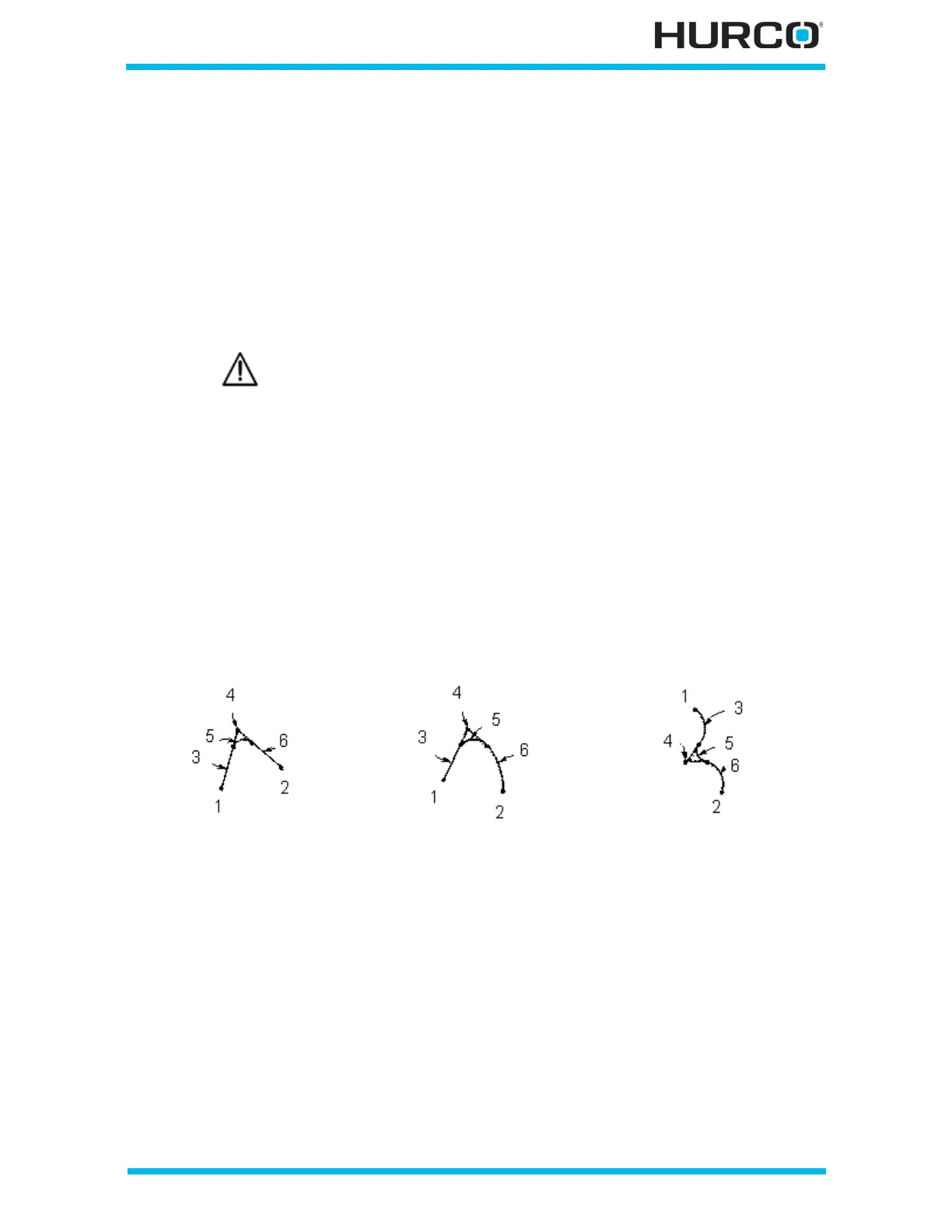
A blend arc joins two other segments and is tangent to both. A blend arc can be used to
join these types of segments:
•two Line segments.
• a Line segment and an Arc segment.
•two Arc segments.
The segments to be joined must have a theoretical point of intersection. If the only
information known about an arc is its radius, it is easier to program it as a blend arc (if
the segments intersect). The diagram below illustrates some examples of blend arcs.
Figure 2–122. Blend Arc Examples
Linear Y-Axis Motion is limited. The amount of Y travel is affected by
the X position and by any X-Axis tool length offset.
Two Lines joined by a
Blend Arc
Line and Arc Joined by a
Blend Arc
Two Arcs Joined by a
Blend Arc
1 X/Y Start
2 X/Y End
3 Segment 1 (Line)
4 Segment 1 End/
Segment 3 Start
(Point of Intersection)
5 Segment 2 (Blend Arc)
6 Segment 3 (Line)
1 X /Y Start
2 X/Y End
3 Segment 1 (Line)
4 Segment 1 End/
Segment 3 Start
(Point of Intersection)
5 Segment 2 (Blend Arc)
6 Segment 3 (Arc)
1 X/Y Start
2 X/Y End
3 Segment 1 (Arc)
4 Segment 1 End/
Segment 3 Start
(Point of Intersection)
5 Segment 2 (Blend Arc)
6 Segment 3 (Arc)
 Loading...


