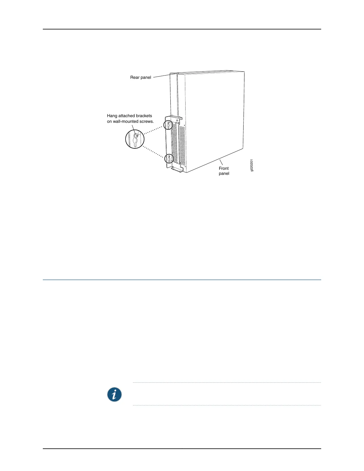
Figure 47: Mounting the Switch on a Wall
Hang attached brackets
on wall-mounted screws.
g020201
Front
panel
Rear panel
5. Tighten the mounting screws by using the screwdriver.
Related
Documentation
Connecting AC Power to an EX4300 Switch on page 185•
• Connecting DC Power to an EX4300 Switch on page 188
• Connecting and Configuring an EX Series Switch (CLI Procedure) on page 215
• Connecting and Configuring an EX Series Switch (J-Web Procedure) on page 218
• Wall-Mounting Warning for EX4300 Switches on page 298
Installing and Removing EX4300 Switch Hardware Components
The EX4300 switch chassis is a rigid sheet-metal structure that houses the hardware
components. The field-replaceable units (FRUs) in EX4300 switches are:
•
Power supplies
•
Fan modules
•
Uplink module
•
Transceiver
The power supply (AC or DC), fan module, uplink module, and transceivers are
hot-removable and hot-insertable: You can remove and replace them without powering
off the switch or disrupting switch functions.
NOTE: You must remove a fan module only for replacement.
See these topics for instructions for installing and removing components:
Copyright © 2017, Juniper Networks, Inc.176
EX4300 Switch Hardware Guide