Table 16: Uplink Modules Used in 32-Port EX4300 Switches (continued)
FigureModel NumberUplink Module Name
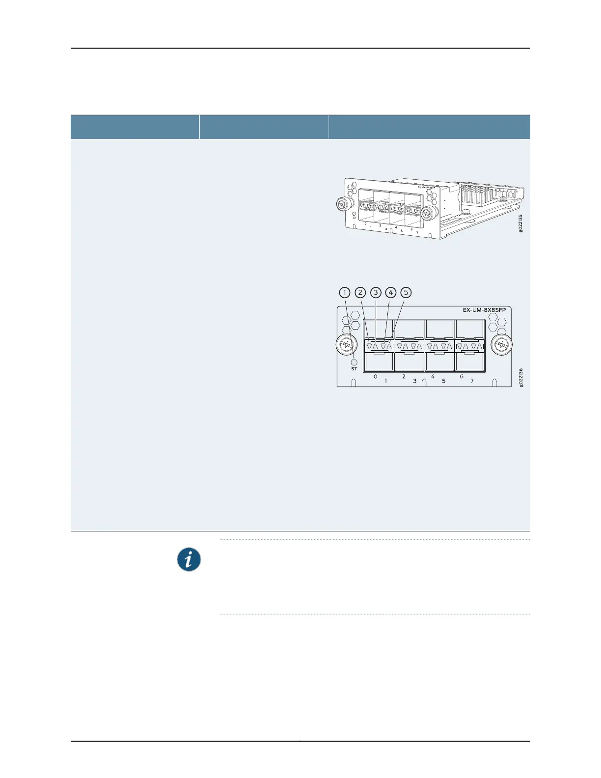
Figure 17: 8-Port 10-Gigabit Ethernet
SFP+ Uplink Module
Figure 18: LEDs on the 8-Port 10-Gigabit
Ethernet SFP+ Uplink Module
1. Status LED of the uplink module
2. Link activity LED of the lower port
3. Link activity LED of the upper port
4. Status LED the lower port
5. Status LED the upper port
EX-UM-8X8SFP8-port 10-Gigabit Ethernet SFP+
uplink module
NOTE: When you install an uplink module in the switch or replace an uplink
modulewith another uplink module, the switch detectsthe ports on the uplink
module. The switch creates the required interfaces when transceivers are
installed in these ports.
The SFP+ uplink module ports can operate either in 10-gigabit or in 1-gigabit mode
depending on the transceiver you install in them. The operating mode for an SFP+ uplink
module is shown in the output of the show chassis pic fpc-slot slot number pic-slot slot
number command.
Each port on the uplink modules has a pair of LEDs that indicate the link activity and
status of the port. See “Network Port, Built-In QSFP+ Port, Uplink Port, and Uplink Module
35Copyright © 2017, Juniper Networks, Inc.
Chapter 2: Chassis Components and Descriptions