Port LEDs on EX4300 Switches” on page 39 for details about the status and link activity
LEDs.
SFP+ uplink modules are shipped with dust covers installed in the ports. QSFP+ uplink
module is shipped with a dust cover installed in one of the ports.
Related
Documentation
Pluggable Transceivers Supported on EX4300 Switches on page 109•
• SFP+ Direct Attach Copper Cables for EX Series Switches on page 134
• Installing an Uplink Module in an EX4300 Switch on page 241
• EX Series Switches Interfaces Overview
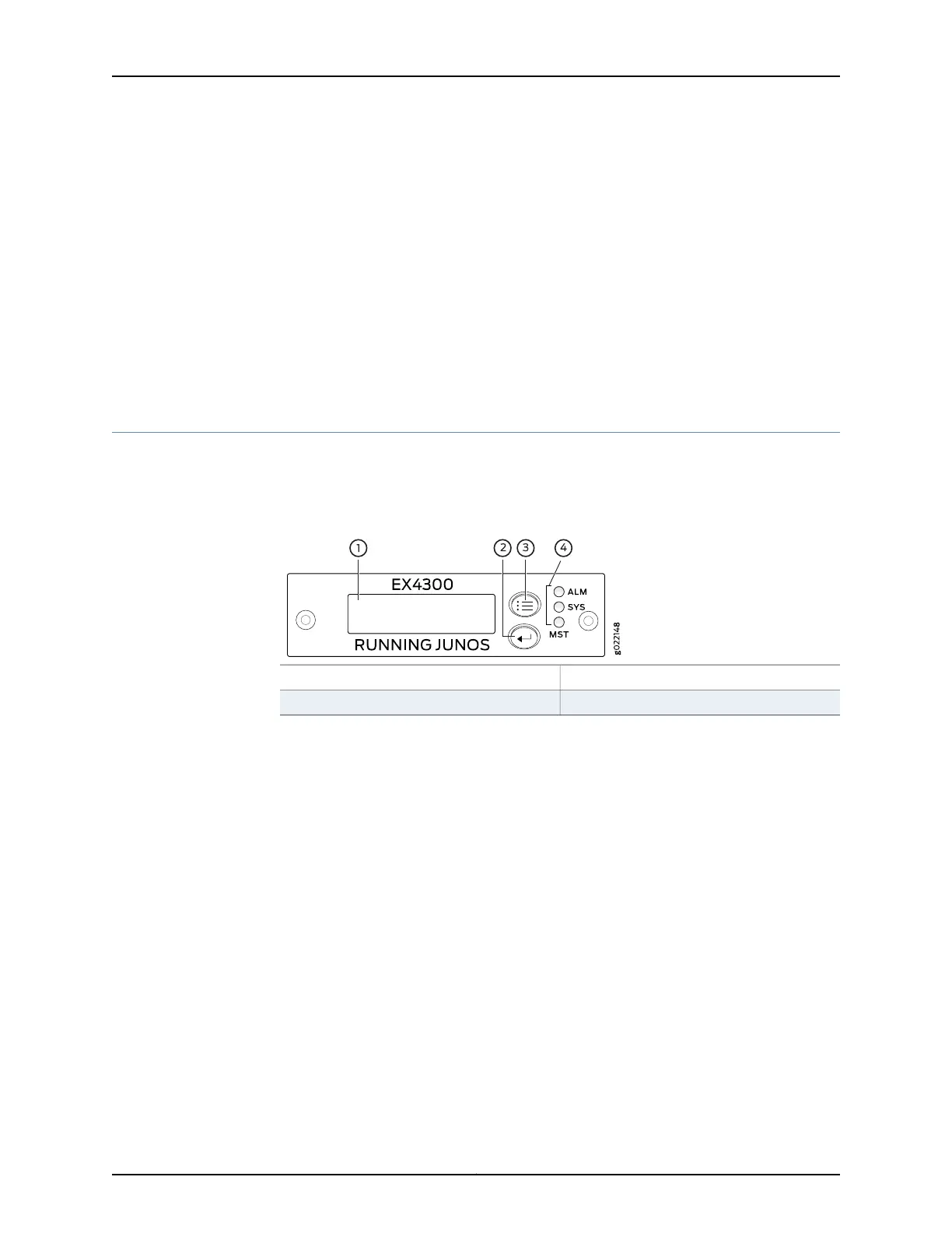
Chassis Status LEDs on EX4300 Switches
An EX4300 switch has three chassis status LEDs (labeled ALM, SYS, and MST) on the
right of the LCD panel, next to the Menu and Enter buttons (see Figure 19 on page 36).
Figure 19: Chassis Status LEDs in an EX4300 Switch
3—1— LCD panel Menu buttonLCD panel
4—2— Chassis status LEDsLCD panel Enter button
Table 17 on page 37 describes the chassis status LEDs on an EX4300 switch, their colors
and states, and the status they indicate. You can view the colors of the three LEDs
remotely through the CLI by issuing the operational mode command show chassis led.
Copyright © 2017, Juniper Networks, Inc.36
EX4300 Switch Hardware Guide