NOTE: The fan module slots are at the left end of the rear panel on 24-port
and 48-port switches, and at the right end on 32-port switches.
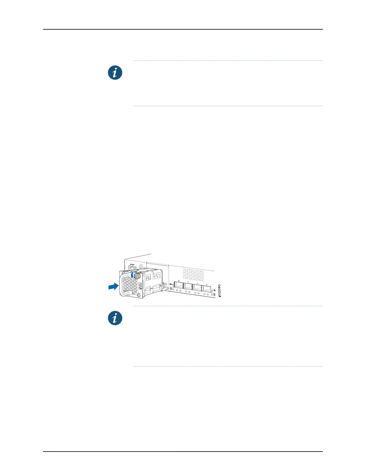
Figure67on page 230 shows howto install a fanmodule in 24- port or 48-port
switches. The procedure is the same for 32-port switches.
1. Ensure that you have the correct fan module. The label AIR IN (AFI) or AIR OUT (AFO)
on the fan module must match the label AIR IN (AFI) or AIR OUT (AFO) on the installed
power supply.
2. Attach the ESD grounding strap to your bare wrist, and connect the strap to the ESD
point on the chassis.
3. Remove the fan module from its bag.
4. Hold the handle of the fan module with one hand and support the weight of the module
with the other hand. Place the fan module in the fan module slot on the rear panel of
the switch and slide it in until it is fully seated.
5. Tighten the captive screws on the faceplate of the fan module by using your fingers.
If you are unable to tighten the captive screws by using your fingers, use the screwdriver.
Figure 67: Installing a Fan Module in a 24-Port EX4300 Switch
NOTE: If you have a Juniper J-Care service contract, register any addition,
change, or upgrade of hardware components at
https://www.juniper.net/customers/support/tools/updateinstallbase/ . Failure
to do so can result in significant delays if you need replacement parts. This
note does not apply if you replace existing components with the same type
of component.
Related
Documentation
Removing a Fan Module from an EX4300 Switch on page 231•
• Cooling System and Airflow in an EX4300 Switch on page 43
• Field-Replaceable Units in EX4300 Switches on page 26
• EX4300 Switches Hardware Overview on page 3
Copyright © 2017, Juniper Networks, Inc.230
EX4300 Switch Hardware Guide