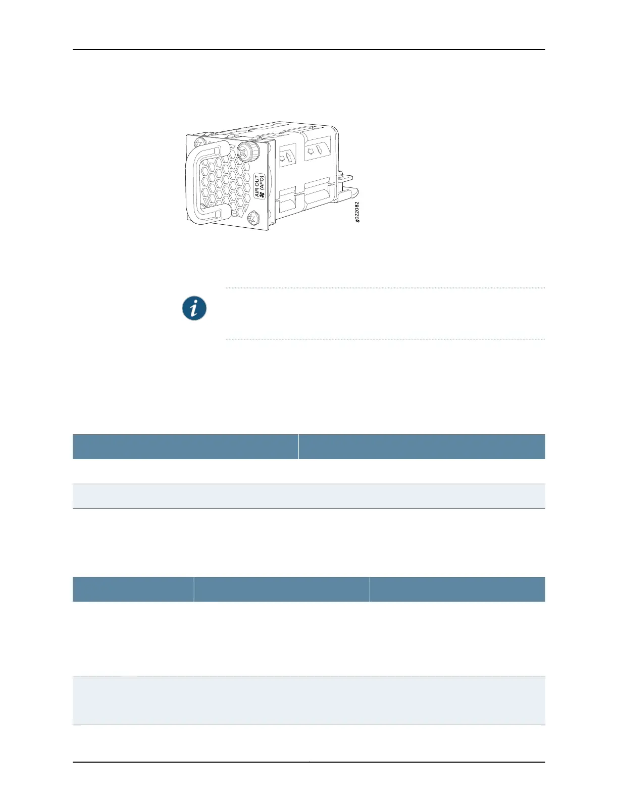
Figure 27: Fan Module Used in an EX4300 Switch
You must remove only one fan module at a time for replacement from the rear panel of
the chassis. The switch continues to operate for a limited period of time (30 seconds)
during the replacement of the fan module without thermal shutdown.
NOTE: Both the fan modules must be installed for optimal functioning of
the switch.
The fan modules are available in two models that have different airflow
directions—back-to-front (air enters through the back of the switch), indicated by label
AIR IN (AFI), and front-to-back (air exhausts through the back of the switch), indicated
by label AIR OUT (AFO). Table 24 on page 44 lists the available fan module models and
the direction of airflow in them.
Table 24: Fan Modules in EX4300 Switches
Label on the Fan ModuleFan Module
AIR OUT (AFO)EX4300-FAN
AIR IN (AFI)EX4300-FAN-AFI
Airflow Direction in EX4300 Switch Models
Table 25 on page 44 shows the direction of airflow in EX4300 switch models as shipped.
Table 25: Airflow Direction in EX4300 Switch Models
Direction of AirflowFan Modules and Power SupplyModel Number
Front-to-back—that is, air intake to cool the
chassisis through the ventson the front panel
of the chassis and hot air exhausts through
the vents on the rear panel of the chassis.
The switch ships with two fan modules and
an AC power supply, each with a label AIR
OUT (AFO).
•
EX4300-24T
•
EX4300-24P
•
EX4300-32F
•
EX4300-48T
•
EX4300-48P
Front-to-back—that is, air intake to cool the
chassisis through the ventson the front panel
of the chassis and hot air exhausts through
the vents on the rear panel of the chassis.
The switch ships with two fan modules and a
DC power supply, each with a label AIR OUT
(AFO).
•
EX4300-32F-DC
•
EX4300-48T-DC
Copyright © 2017, Juniper Networks, Inc.44
EX4300 Switch Hardware Guide