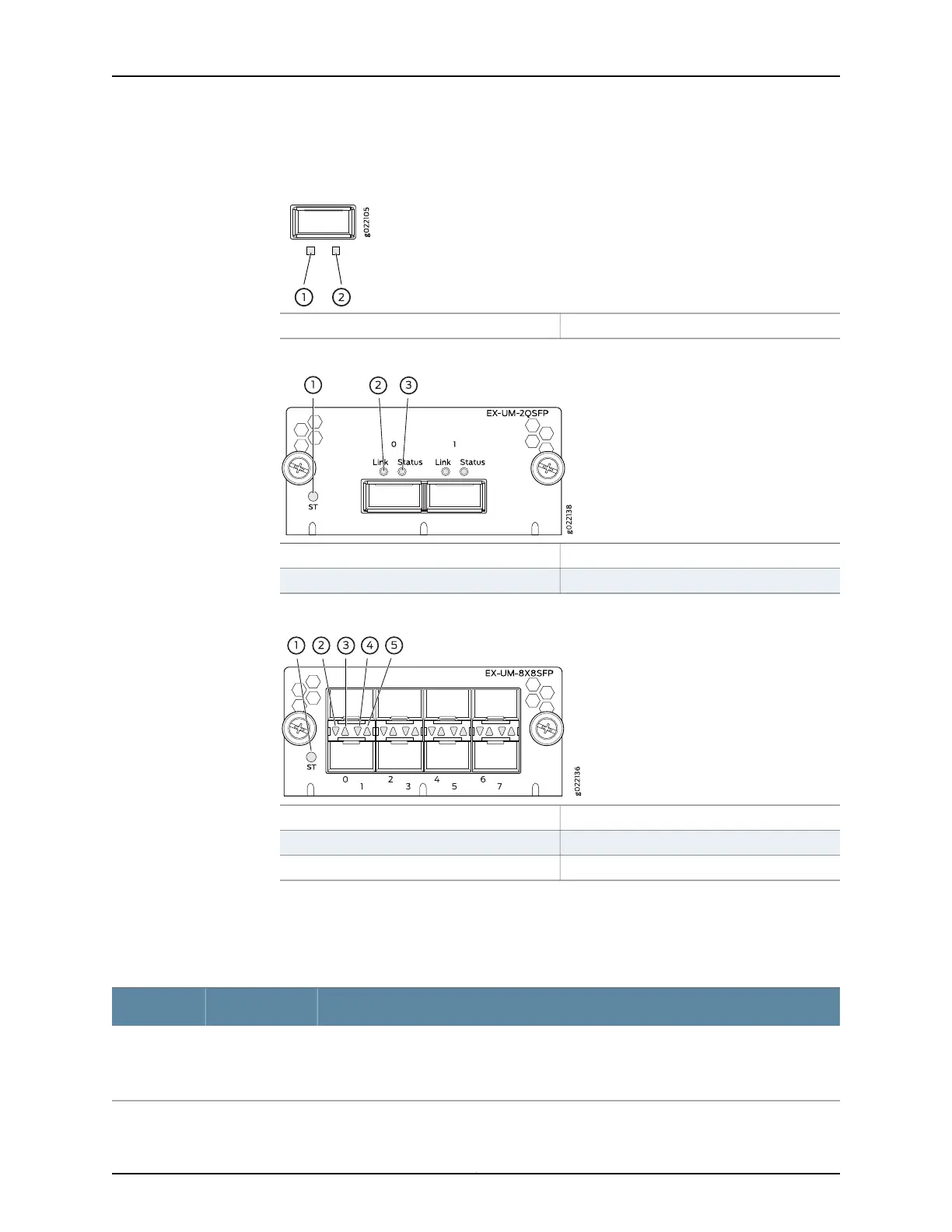
Figure 24: LEDs on the SFP+ Uplink Ports and on the SFP+ Uplink Module
Ports on the 4-Port SFP+ Uplink Module
2—1— Status LEDLink activity LED
Figure 25: LEDs on the QSFP+ Uplink Module Ports
3—1— Status LED of the uplink module portStatus LED of the uplink module
2—Link activity LED of the uplink module port
Figure 26: LEDs on the SFP+ Ports on the 8-Port SFP+ Uplink Module
4—1— Status LED the lower portStatus LED of the uplink module
5—2— Status LED the upper portLink activity LED of the lower port
3—Link activity LED of the upper port
The Table 20 on page 40 describes the link activity LED on 10/100/1000BASE-T network
ports, SFP network ports, SFP+ uplink ports, SFP+ uplink module ports, built-in QSFP+
ports, and QSFP+ uplink module ports.
Table 20: Link/Activity LED
State and DescriptionColorLED
•
Blinking—The port and the link are active, and there is link activity.
•
On steadily—The port and the link are active, but there is no link activity.
•
Off—The port is not active.
GreenLink activity
Copyright © 2017, Juniper Networks, Inc.40
EX4300 Switch Hardware Guide