•
Fan modules with different airflow labels (AIR IN (AFI) and AIR OUT (AFO))
in the same chassis.
•
Power supplies with different airflow labels (AIR IN (AFI) and AIR OUT
(AFO)) in the same chassis.
•
Fan modules and power supplies with different airflow labels (AIR IN (AFI)
and AIR OUT (AFO)) in the same chassis.
•
AC and DC power supplies in the same chassis.
EX4300 Switch Components
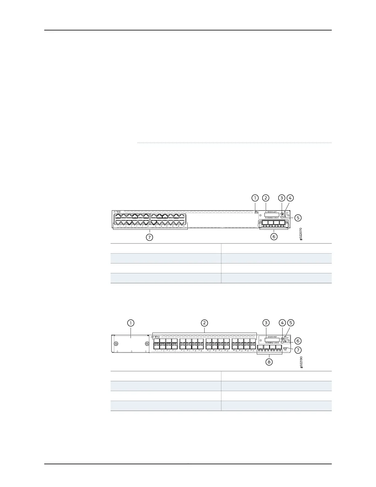
Figure7 on page 13 shows the components on the front panel of a 24-port EX4300 switch
(with an SFP+ uplink module installed).
Figure 7: Components on the Front Panel of a 24-Port EX4300 Switch
5—1— LCD panel Enter buttonMini-USB console port
6—2— SFP+ uplink module (optional)LCD panel
7—3— Network portsLCD panel Menu button
4—Chassis status LEDs
Figure 8 on page 13 shows the components on the front panel of a 32-port EX4300
switch.
Figure 8: Components on the Front Panel of a 32-Port EX4300 Switch
5—1— Chassis status LEDsCover panel for uplink module slot
6—2— LCD panel Enter buttonSFP network ports
7—3— Mini-USB console portLCD panel
8—4— SFP+ uplink portsLCD panel Menu button
Figure 9 on page 14 shows the components on the front panel of a 48-port EX4300
switch (with an SFP+ uplink module installed).
13Copyright © 2017, Juniper Networks, Inc.
Chapter 1: System Overview