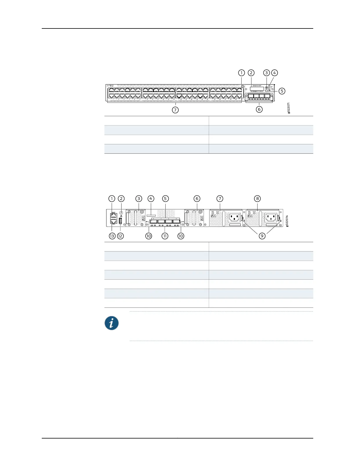
Figure 9: Components on the Front Panel of a 48-Port EX4300 Switch
5—1— LCD panel Enter buttonMini-USB console port
6—2— SFP+ uplink module (optional)LCD panel
7—3— Network portsLCD panel Menu button
4—Chassis status LEDs
Figure 10 on page 14 shows the components on the rear panel of a 24-port and 48-port
EX4300 switch (with two AC power supplies and two fan modules installed).
Figure 10: Components on the Rear Panel of a 24-Port and 48-Port
EX4300 Switch
8—1— AC power supply in slot 1Management port
9—2— Power supply slot numbersESD point
10—3— Fan module slot numbers and LEDsFan module in slot 0
11—4— QSFP+ port LEDsSerial number label
12—5— USB portQSFP+ ports
13—6— Console portFan module in slot 1
7—AC power supply in slot 0
NOTE: DC power supplies are installed in the power supply slots in models
that use DC power.
Figure 11 on page 15 shows the components on the rear panel of a 32-port EX4300 switch
(with two AC power supplies and two fan modules installed).
Copyright © 2017, Juniper Networks, Inc.14
EX4300 Switch Hardware Guide