4. Taking care not to touch power supply pins, leads, or solder connections, remove the
power supply from the bag.
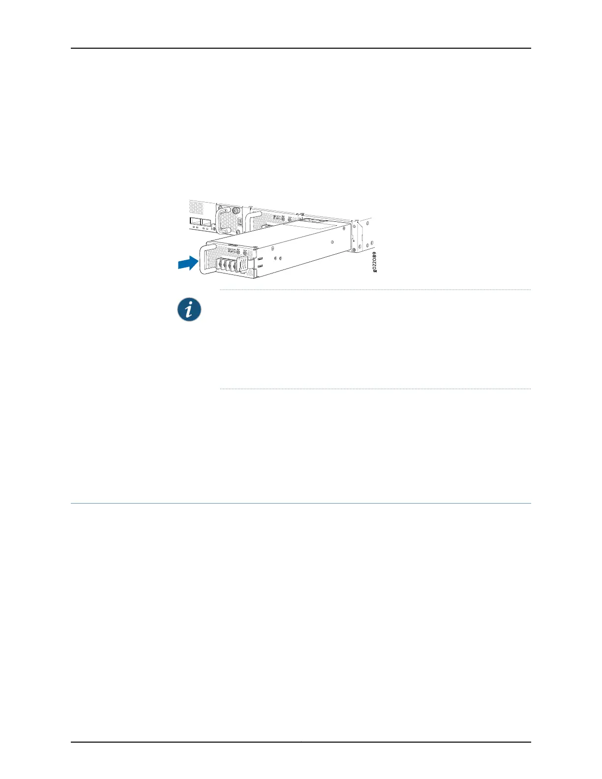
5. Using both hands, place the power supply in the power supply slot on the rear panel
of the switch and slide it in until it is fully seated and the ejector lever fits into place.
Figure 71: Installing a DC Power Supply in an EX4300 Switch
NOTE: If you have a Juniper J-Care service contract, register any addition,
change, or upgrade of hardware components at
https://www.juniper.net/customers/support/tools/updateinstallbase/ . Failure
to do so can result in significant delays if you need replacement parts. This
note does not apply if you replace existing components with the same type
of component.
Related
Documentation
Removing a DC Power Supply from an EX4300 Switch on page 238•
• Connecting DC Power to an EX4300 Switch on page 188
• DC Power Supply in EX4300 Switches on page 57
• EX4300 Switches Hardware Overview on page 3
Removing a DC Power Supply from an EX4300 Switch
The power supply in EX4300 switches is a hot-removable and hot-insertable
field-replaceable unit (FRU) installed in the rear panel of the switch: You can remove
and replace it without powering off the switch or disrupting switch functions.
Before you begin removing a power supply from the switch:
•
Ensure you understand how to prevent electrostatic discharge (ESD) damage. See
“Prevention of Electrostatic Discharge Damage” on page 313.
Ensure that you have the following parts and tools available to remove the power supply
from the switch chassis:
•
ESD grounding strap
•
Phillips (+) screwdriver, number 2
Copyright © 2017, Juniper Networks, Inc.238
EX4300 Switch Hardware Guide