3. Locate the power cord and power cord retainer shipped with the switch; the cords
have plugs appropriate for your geographical location. See “AC Power Cord
Specifications for an EX4300 Switch” on page 100.
4. Push the end of the retainer strip into the hole next to the inlet on the power supply
face plate until it snaps into place. Ensure that the loop in the retainer strip faces
toward the power cord.
5. Press the small tab on the retainer strip to loosen the loop. Slide the loop until you
have enough space to insert the power cord coupler into the inlet.
6. Insert the power cord coupler firmly into the inlet.
7. Slide the loop toward the power supply until it is snug against the base of the coupler.
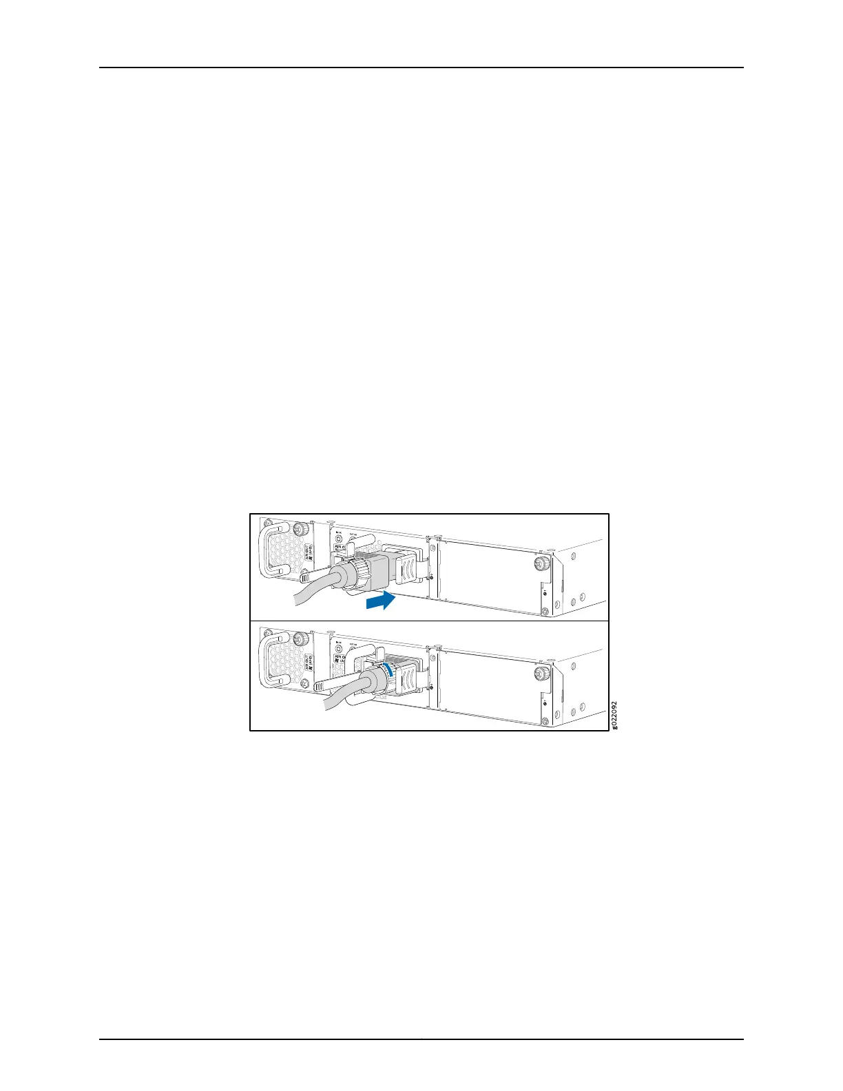
8. Press the tab on the loop and draw out the loop into a tight circle (see
Figure 50 on page 187).
Figure 50: Connecting an AC Power Cord to an AC Power Supply in an
EX4300 Switch
9. If the AC power source outlet has a power switch, set it to the OFF (O) position.
10. Insert the power cord plug into an AC power source outlet.
11. If the AC power source outlet has a power switch, set it to the ON (|) position.
12. Verify that the IN OK and OUT OK LEDs on each power supply are lit green.
If the OUT OK LED is lit amber, remove power from the power supply, and replace the
power supply (see “Removing an AC Power Supply from an EX4300 Switch” on
page 235). Do not removethe power supply until you have a replacement power supply
187Copyright © 2017, Juniper Networks, Inc.
Chapter 12: Connecting the Switch to Power