16-6 Sound Recording Setup Model 831 Manual
Step 1 For each combination of Instrument Gain (0 or 20
dB) and (Low or High), enter the peak overload level values
in the 3rd row. For the High range use the values determined
as described in "Peak Overload/Noise Level" on page 16-5.
For the Low Range, subtract 33 dB from the High range
value.
Step 2 For each column, subtract 93 dB from each peak
overload level to obtain the lower level of A/D range and
enter this in the 4th row.
Step 3 For each column, enter the value of noise floor in
the 5th row.
Step 4 For each column, determine the sound recording
range. The lower limit will be the larger of the lower level of
A/D range and the instrument noise floor. The upper limit
will be the peak overload level
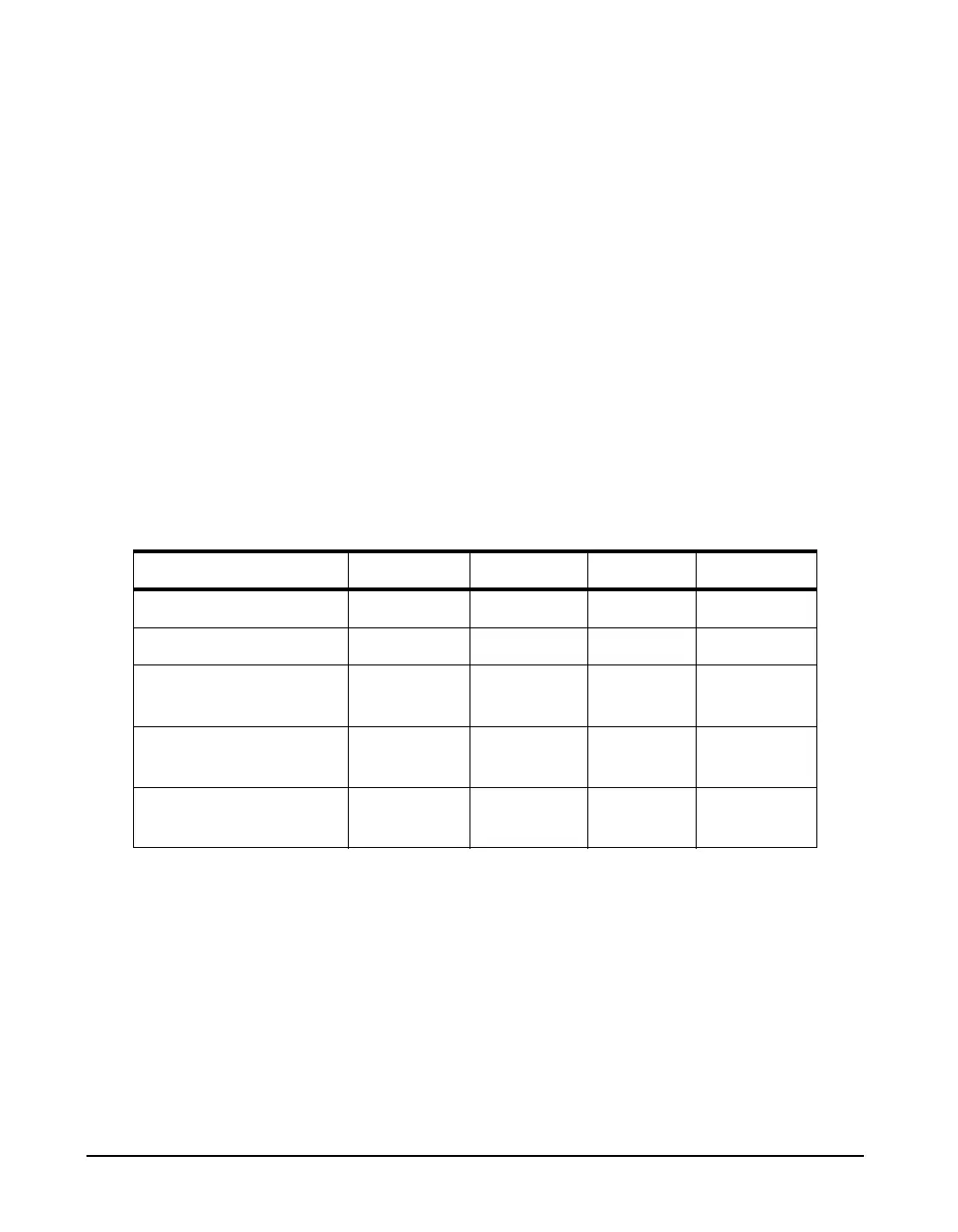
TABLE 16-1 Sound Recording Range Calculation: Microphone Sensitivity of 50 mV/Pa
The quality of a sound recording will depend upon the levels
of sound being recorded and the choice of instrument gain
and range used in the instrument setup. Should the sound
level exceed the peak overload level, there will be clipping
of the signal which will introduce distortion into the
playback. If the sound level drops below the lower limit of
the sound recording range, its signal will be lost in noise
during playback. Thus, the selection of instrument gain and
Instrument Gain 0 dB 0 dB 20 dB 20 dB
Range High Low High Low
Peak Overload Level 143 dB 110 dB 123 dB 90 dB
Lower Level of A/D
Range
50 dB 17 dB 30 dB -7 dB
Instrument Noise
Floor
23 dB 23 dB 21 dB 21 dB
Sound Recording
Range
50 - 143 dB 23 - 110
dB
30 - 123
dB
21 - 90 dB