Model 831 Manual Model 831 Specifications A-9
I/O Connector Specification
The 831 meter includes an I/O connector for peripherals and external power, or other external devices.
For example:
•CBL143 and CBL151 cables: these cables permit the Model 831 to be powered from external
12 V batteries.
•CBL154 cable: used to obtain power from a battery when used with the 426A12
•831-INT: integrates the Model 831 with outdoor microphone units (426A12 and PRM2100K)
and weather transducers
•PRM2103, 426A12 and 2101K: Model 831 provides control signals to these outdoor
microphone units when not used with 831-INT
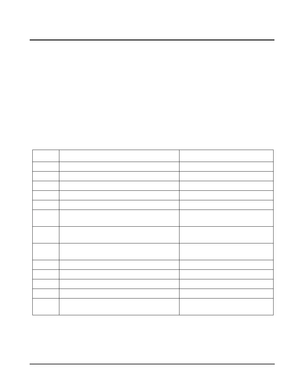
I/O Connector Pinouts
The pinouts for the I/O Connector are as shown in Table A-9 " Model 831 I/O Pinouts".
Pin # Description Signal Type
1 Ground, Digital and Power Supply Ground
2 Logic Out 1, Logic Control Output Output, 0 to +2.7 V
3 831 Activity Output, 0 to +2.7 V
4 Logic In, Logic Control Input Input, 0 to +5 V
5 Ground, Digital and Power Supply Ground
6, 7 Vext, External Power Input Input, +10.8 to +30 V, 0.5 A
auto-resetting PTC fuse
8 SensorClk_L, LD 426A12 digital sensor clock Output, open drain, +20 V max. open
and 50 mA max. closed
9 SensorDIO, LD 426A12 digital sensor data Bi-directional, +2.7 to +5 V logic,
open drain
10 CalOn_H, LD 426A12 calibration signal on Output, 0 to +2.7 V
11 Ovld, LD 426A12 overload detection signal Input, 0 to +5 V
12 Mains Power Status; OK when +2.7 V Input, 0 to +2.7 V
13 +2.7 V to supply logic switches Output, +2.7 V thru 220
14 WindSpeedIn, Pulse input for wind speed
sensors
Input, +5 Vpp max.
Table A-9 Model 831 I/O Pinouts