A-10 Model 831 Specifications Model 831 Manual
1. To enable the “Logic In, Logic Control Input” feature, when making your own cable, pin 12 (Mains
Power Status) must be driven by a resistance lower than about 20k
. This may be done by connecting
a 10k
resistor from pin 12 to either pin 13 (+2.5V, to simulate running on Mains power) or to pin 1 or
5 (Ground, to indicate running on external battery power). Pin 4 needs to be driven high to assert the
Logic In and pulled low to de-assert the input. It should not be left floating. This can be done with a
momentary push-button switch from pin 4 to pin 13 with a 10k
pull down resistor to ground (10k
from pin 4 to pin 1 or 5).
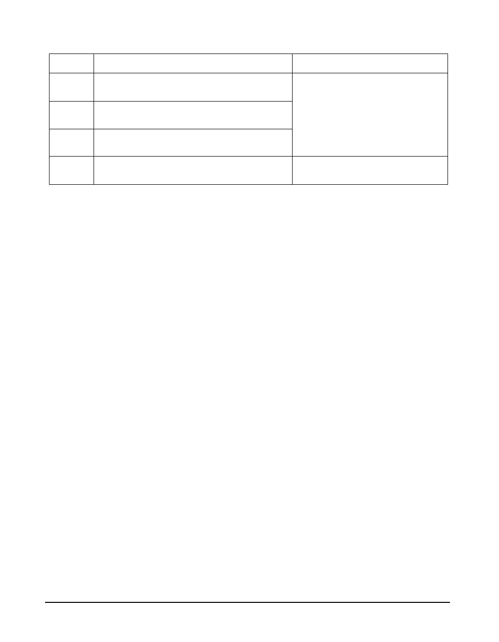
15 Vwthr1, Analog to Digital Converter Input,
Wind Direction
Input, 0 to +2.048 V, 100k load,
scale with series resistor
16 Vwthr2, Analog to Digital Converter Input,
Temperature
17 Vwthr3, Analog to Digital Converter Input,
Humidity
18 Analog Ground, Signal ground for pins 15
through 17
Ground
Pin # Description Signal Type
Table A-9 Model 831 I/O Pinouts