Lenze · 8400 HighLine · Reference manual · DMS 12.0 EN · 06/2017 · TD23 1348
17 Function library
17.1 Function blocks | L_DFRFG_1
_ _ _ _ _ _ _ _ _ _ _ _ _ _ _ _ _ _ _ _ _ _ _ _ _ _ _ _ _ _ _ _ _ _ _ _ _ _ _ _ _ _ _ _ _ _ _ _ _ _ _ _ _ _ _ _ _ _ _ _ _ _ _ _
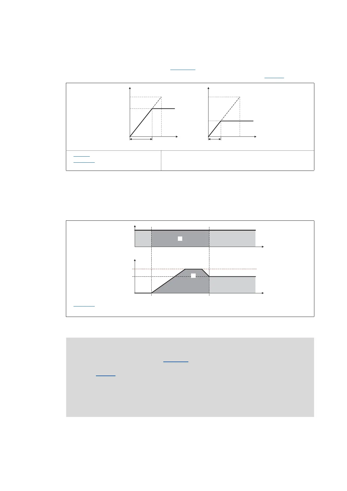
• The acceleration or deceleration in the synchronous point results from the
acceleration/deceleration time set in C01076/1
.
• Reference for the acceleration/deceleration time is the reference speed (C00011
):
[17-27] Connection between acceleration time and acceleration
• Based on the input speed of the master axis, a setpoint angle is calculated from the starting
time onwards which leads the actual angle of the slave.
• Dependent on the master speed and the settings for acceleration and offset, the FB may travel
oversynchronously for reducing the angular difference, i.e. nOut_v is higher than nIn_v:
[17-28] Speed/time diagram
C00011: Reference speed
C01076/1
: Acceleration/deceleration
time
Effective target speed
Required time
C01077/1: Maximum speed
Identical surface below the speed profile that represents the covered path.
Note!
• Set the maximum speed in C01077/1 higher than the master speed to be expected.
The speed is selected on the motor side and is independent of the reference speed
(C00011
). The higher the difference between maximum speed and master speed, the
less time to the synchronous time is required.
• In case of a heavily oscillating input speed it may occur that directly after setting the
bSync status signal to TRUE the FB still executes slight angle corrections.
• Generally avoid acceleration or deceleration processes of the master axis while the
slave axes are synchronising.