11 System bus "CAN on board"
11.11 CANopen objects implemented | I-1201
764
Lenze · 8400 HighLine · Reference manual · DMS 12.0 EN · 06/2017 · TD23
_ _ _ _ _ _ _ _ _ _ _ _ _ _ _ _ _ _ _ _ _ _ _ _ _ _ _ _ _ _ _ _ _ _ _ _ _ _ _ _ _ _ _ _ _ _ _ _ _ _ _ _ _ _ _ _ _ _ _ _ _ _ _ _
Example
Parameter data channel 2 of the inverter with node address 4 shall be activated.
• For this purpose, bit 31 in the subindexes 1 and 2 of the I-1201
object must be set to the value
"0" (≡ "SDO valid").
• The master must send the two "write request" commands to the nodes via the basic SDO
channel.
Identifier calculation
• Identifier (COB-ID) = basic identifier + node address (node ID)
• Basic identifier SDO2 from master to drive: 1600 (0x640)
Identifier = 0x640 + 0x4 = 0x644
• Basic identifier SDO2 from drive to master: 1472 (0x5C0)
Identifier = 0x5C0 + 0x4 = 0x5C4
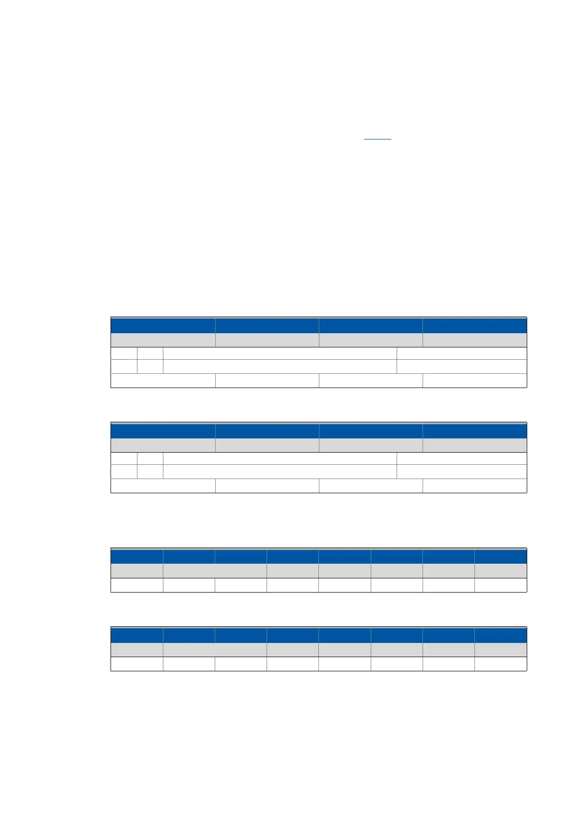
Resulting data (data 1 ... data 4)
[11-7] Data telegram assignment for subindex 1
[11-8] Data telegram assignment for subindex 2
User data assignment
[11-9] User data assignment for writing to subindex 1
[11-10] User data assignment for writing to subindex 2
8th byte 7th byte 6. byte 5th byte
Data 4 Data 3 Data 2 Data 1
Bit 31 Bit 30 Bit 29 ... bit 11 Bit 10 ... bit 0
0 0 Extended identifier = 0 11-bit identifier = 0x644
0x00 0x00 0x06 0x44
8th byte 7th byte 6. byte 5th byte
Data 4 Data 3 Data 2 Data 1
Bit 31 Bit 30 Bit 29 ... bit 11 Bit 10 ... bit 0
0 0 Extended identifier = 0 11-bit identifier = 0x5C4
0x00 0x00 0x05 0xC4
1st byte 2nd byte 3rd byte 4th byte 5th byte 6. byte 7th byte 8th byte
Command Index Subindex Data 1 Data 2 Data 3 Data 4
0x23 0x01 0x12 0x01 0x44 0x06 0x00 0x00
1st byte 2nd byte 3rd byte 4th byte 5th byte 6. byte 7th byte 8th byte
Command Index Subindex Data 1 Data 2 Data 3 Data 4
0x23 0x01 0x12 0x02 0xC4 0x05 0x00 0x00