Direct Fuel Injection
90-8M0050731 MAY 2011 Page 3B-37
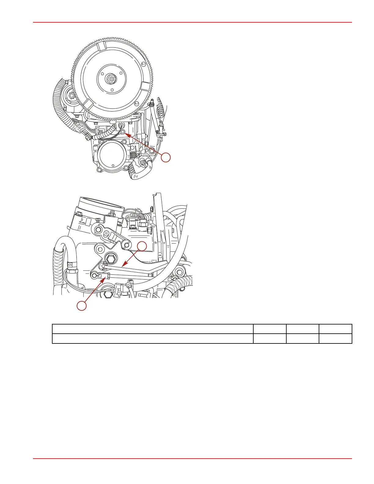
15. Connect the engine harness to the MAP and MAT sensor connectors.
a - MAP sensor
16. Connect the throttle cam link rod and the throttle position sensor link rod.
a - Throttle link rod
b - Throttle position sensor link rod
17. Install the vapor separator and secure with three M8 x 35 screws and washers. Tighten the screws to the specified torque.
Description Nm lb‑in. lb‑ft
Vapor separator mounting screws (M8 x 35) 16 142
18. Install the fuel high‑pressure fuel outlet hose and fuel return hose.
19. Connect the engine harness to the electric fuel pump connectors.
20. Connect the engine harness to the water sensor connector.

 Loading...


