200 MI-42-0001 Rev. 19
TECHNICAL DESCRIPTION: Technical Description
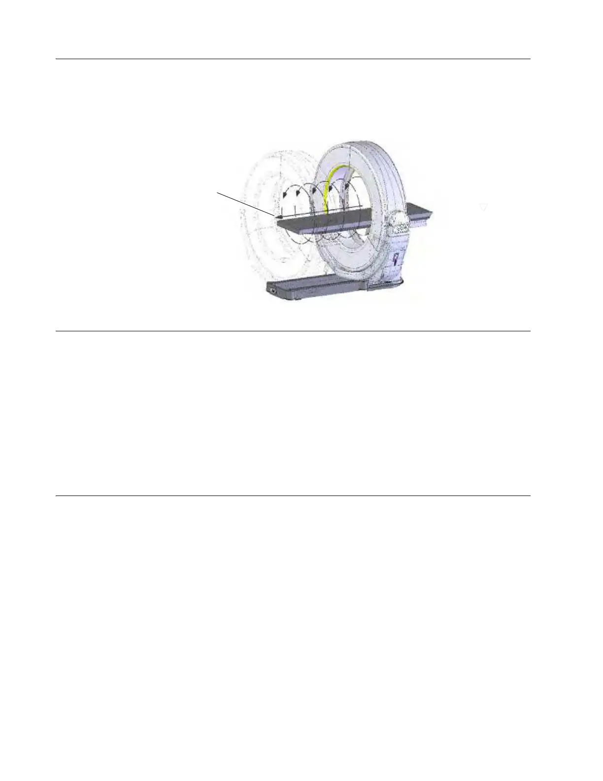
Sequential Axial
Scan Mode
AIRO also offers sequential axial or “Step and Shoot” images of the body. At the start of a sequential,
axial–mode scan, AIRO takes a full 360 degree image of a 31 mm section of the scan area. It then
switches off the X-rays and moves to the next 31 mm scan section along the Z-axis a (Figure 152).
This is repeated as often as needed to cover the required scan area and the discrete scans are
stitched together afterward. This sequence differs from helical mode, in which AIRO moves
continuously in the Z-axis while constantly imaging the scan area.
Figure 152
Unique Features System is mobile: The base incorporates casters, main drive wheel, and an electrical drive system.
The Ring is both lightweight and compact. The entire unit is designed to be driven down hallways,
on limited inclines, through doorways and onto elevators. The user sees the path of travel through
an integrated camera and display. AIRO can be run in any area that has been approved for use by
the responsible organization.
NOTE: The Installation Procedure contains the specific requirements for approved areas.
• Table is detachable and exchangeable: The column accommodates several models of
operating tables and patient supports. The user may change the table and table orientation
relative to the base to suit the procedure.
• Table is portable: The table and patient can be moved to the system on a shuttle. The table and
patient are then transferred onto the system column. Therefore the operating table can be used
in the system.
Main
Sub
asse
mblies
AIRO consists of six main subassemblies:
•Base
• Ring
•Gimbal
• Pendant Holster and Control Panel
• User Interface Pendant
• Trumpf Column (optional)