7.36 Calibration Settings Screens
These screens are used for calibration of machine transducers, servo
degrees to distances, etc.
This screen is divided into the following tabs:
• Nozzle (only for servo carriage systems)
• Injection
• RPM and Inject press
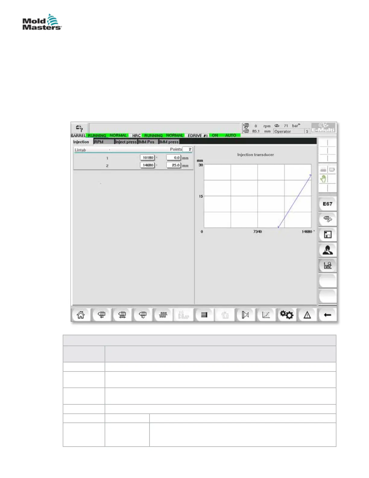
The table shows the values of the individual stages, where they may also be
changed manually. The linearization table is displayed on the right.
Figure 7-40 Calibration settings screen
Table 7-55 Calibration Settings Screen Components
Screen
Components
Description
Nozzle This tab is used for the calibration of carriage feedback to actual carriage position.
Injection
This tab is used for the calibration of injection motor’s rotary position to the screw
position.
RPM
This tab is used for the calibration of the screw motor’s rotational speed to the feed
screw’s rotational speed.
Inject Press This tab is used for calibrating the machine's injection pressure.
Lintab Points Number of points in the linearization table.
1 - n After the auto calibration, the values determined in the process will
be entered automatically into these elds.
All values can be subsequently changed by manual entry.
7-85
© 2020 Mold-Masters (2007) Limited. All Rights Reserved.
E-MULTI CONTROLLER HMI INTERFACE
E-Multi Controller User Manual