Table 7-26 Valve Gate Settings Screen Elements
Screen Components Description
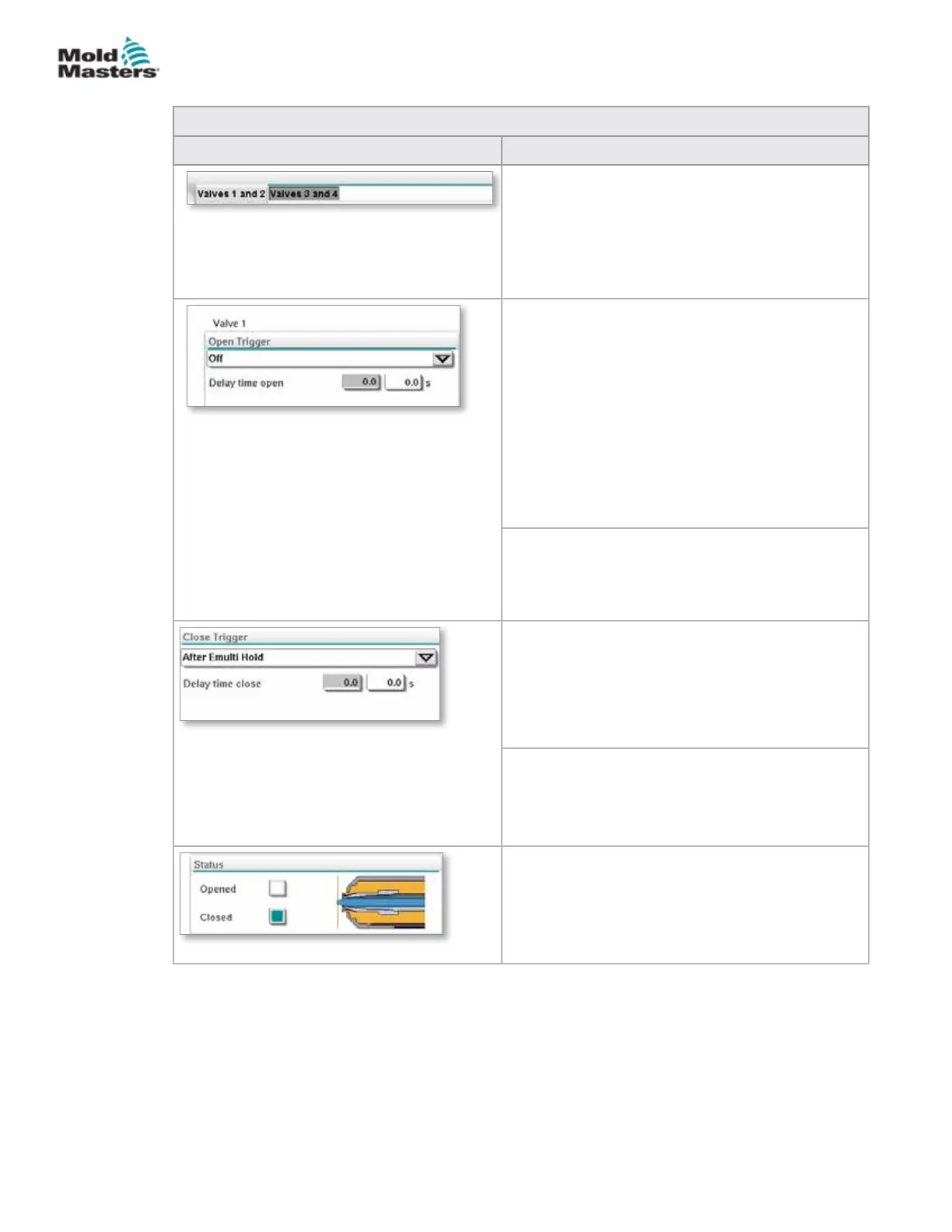
Top Tabs
The tabs at the top of the screen take the user
to the settings for two valve gates at a time (e.g.
Valves 1 and 2; Valves 3 and 4).
For each valve gate the user can set the Open and
Close triggers and timing.
Open Trigger
Drop down options:
O
MoldClosing
ZA6 Mold Closed - signal
ZB3 Eject 1 Bwd- signal (ejection)
ZB4 Eject 1 Fwd- signal (ejection)
ZB5 Core 1 Pos 1- signal (robot)
ZB5 Core 1 Pos 2- signal (robot)
ZB5 Core 2 Pos 1- signal (robot)
ZB5 Core 2 Pos 2- signal (robot)
Delay time open
In addition to the open trigger, a delay time in
seconds may be added to ne tune the valve
movement relative to the trigger signal.
Close Trigger
Drop down options:
After E-Multi Hold
After E-Multi Decompression
After E-Multi Plasticize
Delay time close
In addition to the close trigger, a delay time in
seconds may be added to ne tune the valve
movement relative to the trigger signal.
Current Status
A green indicator box shows whether the valve
gate is currently open or closed.
Valve Gate Settings Screen - continued
7-44
© 2020 Mold-Masters (2007) Limited. All Rights Reserved.
E-MULTI CONTROLLER HMI INTERFACE
E-Multi Controller User Manual