3. Next, check the mechanical function by disconnecting the air supply tube
from the solenoid valve on the support beam and applying compressed
air to the tube. If the vibrator is working properly, it should start to vibrate
when compressed air is applied.
4. If the vibrator is working, reconnect the air line to the valve and
disconnect the valve cable. Apply 24 VDC to pin 1 and 0 VDC to pin 2.
The valve should open and the vibrator should start to vibrate. If the valve
does not move, replace the valve with a known good one.
9.5 Servo Motor Temperature Check
The motor warning and alarm temperatures are factory settings that can only
be changed by a Mold-Masters technician. The default values are:
Warning temperature: 75°C
Alarm temperature: 80°C
The E-Multi controller automatically disables the motors when the alarm
temperature is reached. The motor temperature can be monitored in real time
on the “Drive Monitor Screen” on page 7-74.
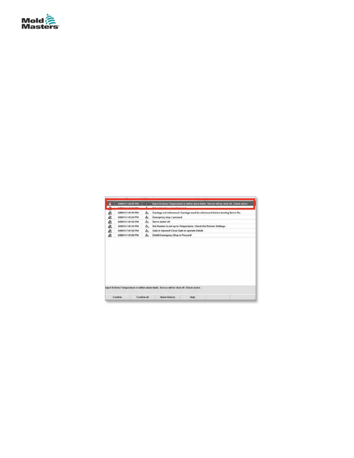
Motor temperature alarms, as shown below, can be seen on the “Alarms
Screen” on page 7-86.
Figure 9-1 Alarms screen with motor temperature alarm
9.6 Troubleshoot the Control System
The control system has several features, which provide an early diagnosis of
faults in the control system.
If the system detects any malfunctions, it displays an error message on the
Alarm screen.
If the system detects any abnormal condition it displays a warning message
on the Alarm screen.
See “Table 9-1 Fault and Warning Messages” on page 9-3. and “Table 9-2
Integrated HRC Warning Messages” on page 9-4.
Vibrator Valve Check - continued
9-2
© 2020 Mold-Masters (2007) Limited. All Rights Reserved.
TROUBLESHOOTING
E-Multi Controller User Manual