Table 7-23 E-Drive Overview Screen Elements
Screen Elements Description
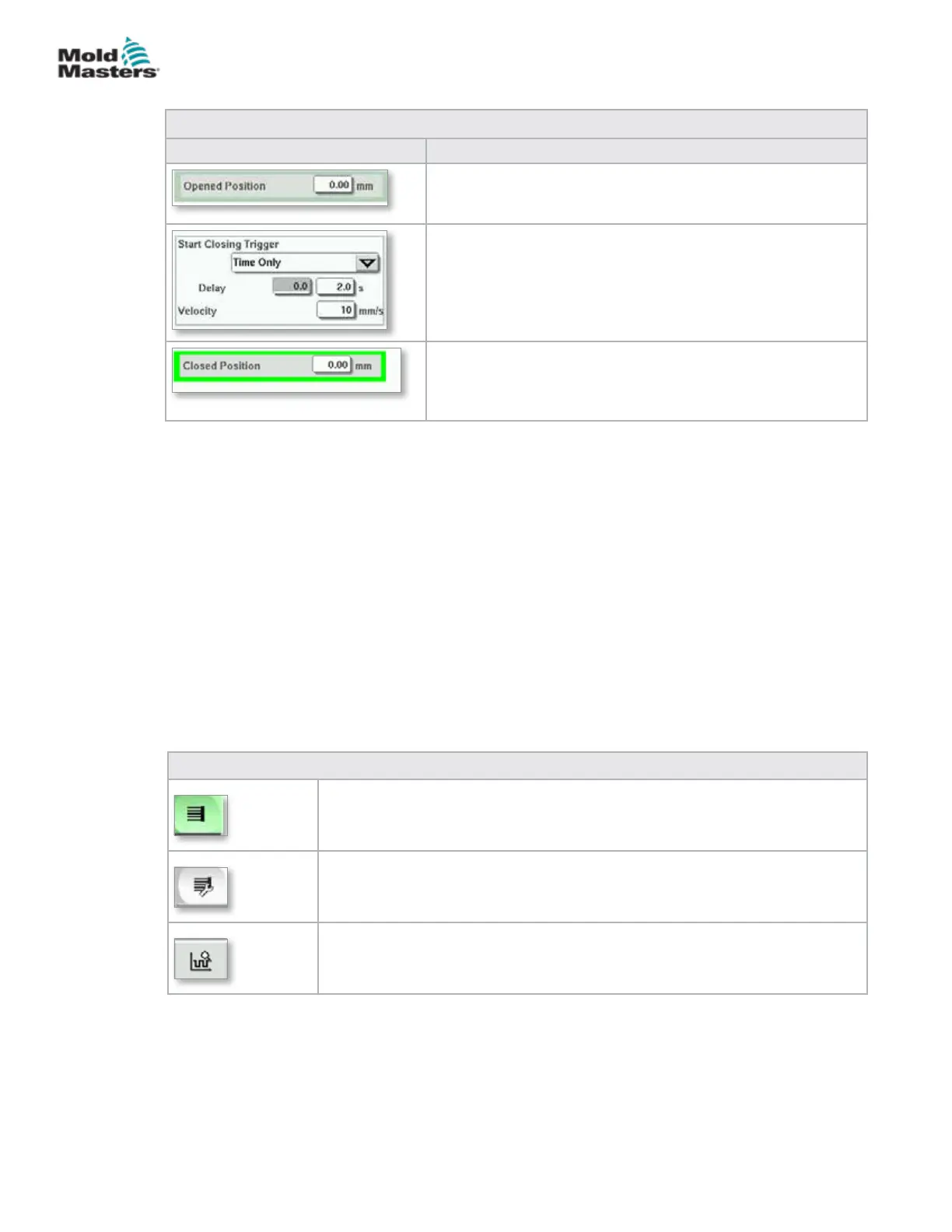
When the trigger conditions in the rst step are met, the
E-Drive controller will move the plate to the [Opened
position]. The actual open position is displayed here.
The [Start Closing Trigger] initiates the E-Drive closing
sequence.
The trigger is selected from the drop down list.
A time delay can also be added.
The [Set Velocity] button opens a dialog where users can
further adjust settings.
When the trigger conditions in the step above are met,
the E-Drive controller will move the plate to the [Closed
Position]. This also represents the starting position for the
next cycle.
7.13.1 Homing
Prior to running the E-Drive, the pin position must rst be referenced.
1. The E-Multi must be in setup mode and the E-Drive Servo must be turned
ON.
2. Press the [Home] button to initiate the automatic reference cycle, which is
described below.
STEP 1 – Move pins all the way back (IN) to the hardstop.
STEP 2 – Move pins all the way forward (OUT) to the hardstop.
STEP 3 – Calibrate this position as 0.00.
STEP 4 – Move the pins to the Closed Position.
3. The E-Drive can now be run in step mode or switched to Auto mode.
Table 7-24 E-Drive Screen Context Menu Buttons
E-Drive Overview Screen
Goes to the Integrated Hot Runner Control Setup screen where Integrated
Hot Runner Control settings can be adjusted.
E-Drive Settings Screen
Goes to the E-Drive Settings screen where settings can be adjusted.
Production Graph - Customizable view.
Overview Screen - continued
7-40
© 2020 Mold-Masters (2007) Limited. All Rights Reserved.
E-MULTI CONTROLLER HMI INTERFACE
E-Multi Controller User Manual