7.7 Hold Settings Screen
CAUTION
Recovery back pressure should never be adjusted below the idle (preload)
pressure.
CAUTION
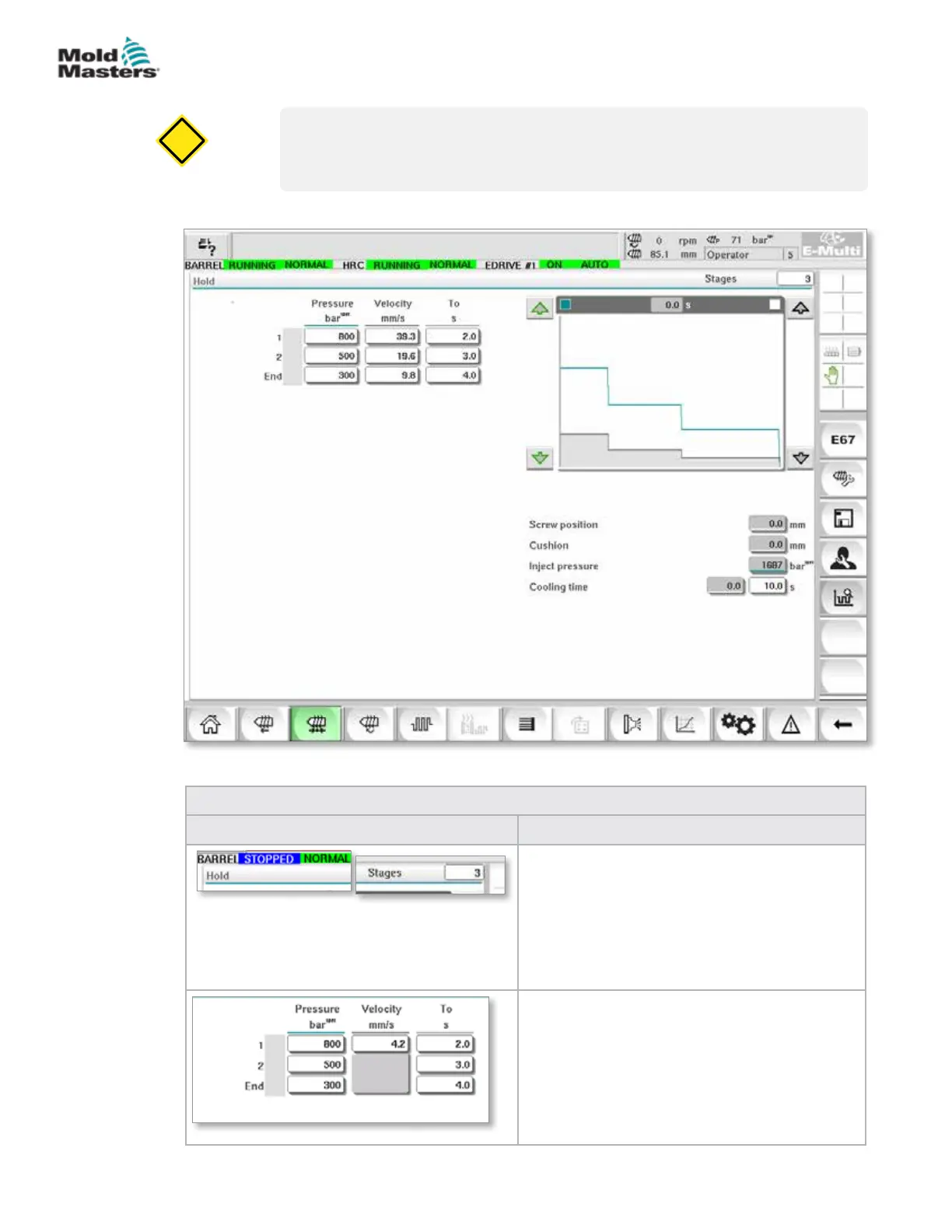
This screen is used for adjusting hold pressure settings.
Table 7-11 Hold Setting Screen Components
Screen Components Description
Hold
This section displays the current hold prole.
The prole is displayed numerically in the elds
on the left and graphically on the right.
The number of hold steps may be adjusted
using the Stages eld at the top left. A maximum
of 10 steps may be selected.
Pressure and Velocity Input Fields
These settings can be adjusted by entering
values directly into these elds.
These elds are used for setting the Pressure
and Velocity between the end position of the
previous stage (in case of stage 1, the end
position of the previous part movement) and the
position specied under the 'To' column.
Figure 7-5 Hold settings screen
7-16
© 2020 Mold-Masters (2007) Limited. All Rights Reserved.
E-MULTI CONTROLLER HMI INTERFACE
E-Multi Controller User Manual