Table 7-21 Utility Screen Elements
Screen Components Description
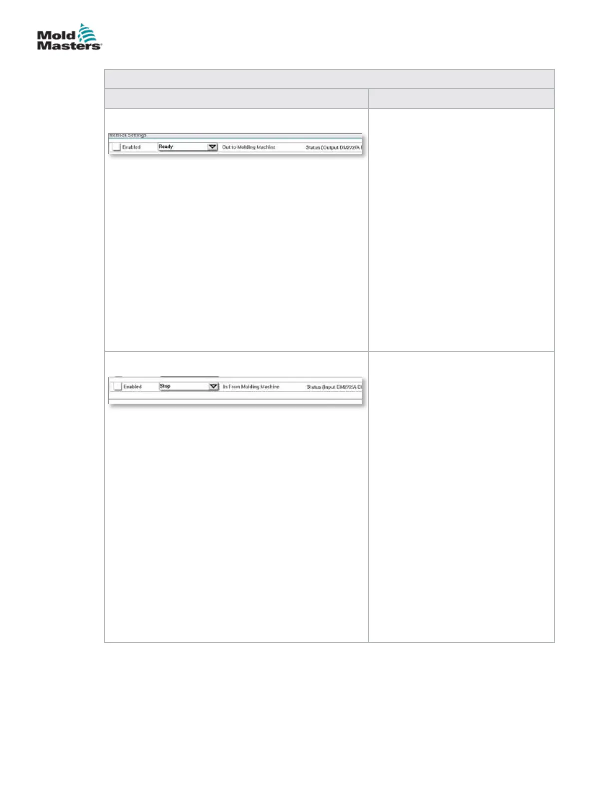
Interlock Settings - Out to Molding
Machine
Enabling this interlock sends a signal
to the molding machine when the
controller is ready (i.e. heat zones are
at temperature, there are no alarms and
controller is in RUN mode).
Tap the drop down box and select
[Ready].
Tap the [Enabled] box and an interlock
window will open.
Tap the checkmark to enable the
interlock.
The status (On = green) / (O = white)
and PLC address are displayed on the
right.
Interlock Settings - In from Molding
Machine
Enabling this interlock accepts a signal
from the molding machine that forces
the E-Multi temperature controller into
the selected mode of operation.
Tap the drop down box and select from
the following Modes:
Stop
Run
Standby
Boost
Tap the [Enabled] box and an interlock
window will open.
Tap the checkmark to enable the
interlock.
The status (On = green) / (O = white)
and PLC address is displayed on the
right.
Utilities Screen (Supervisor Level) - continued
7-36
© 2020 Mold-Masters (2007) Limited. All Rights Reserved.
E-MULTI CONTROLLER HMI INTERFACE
E-Multi Controller User Manual