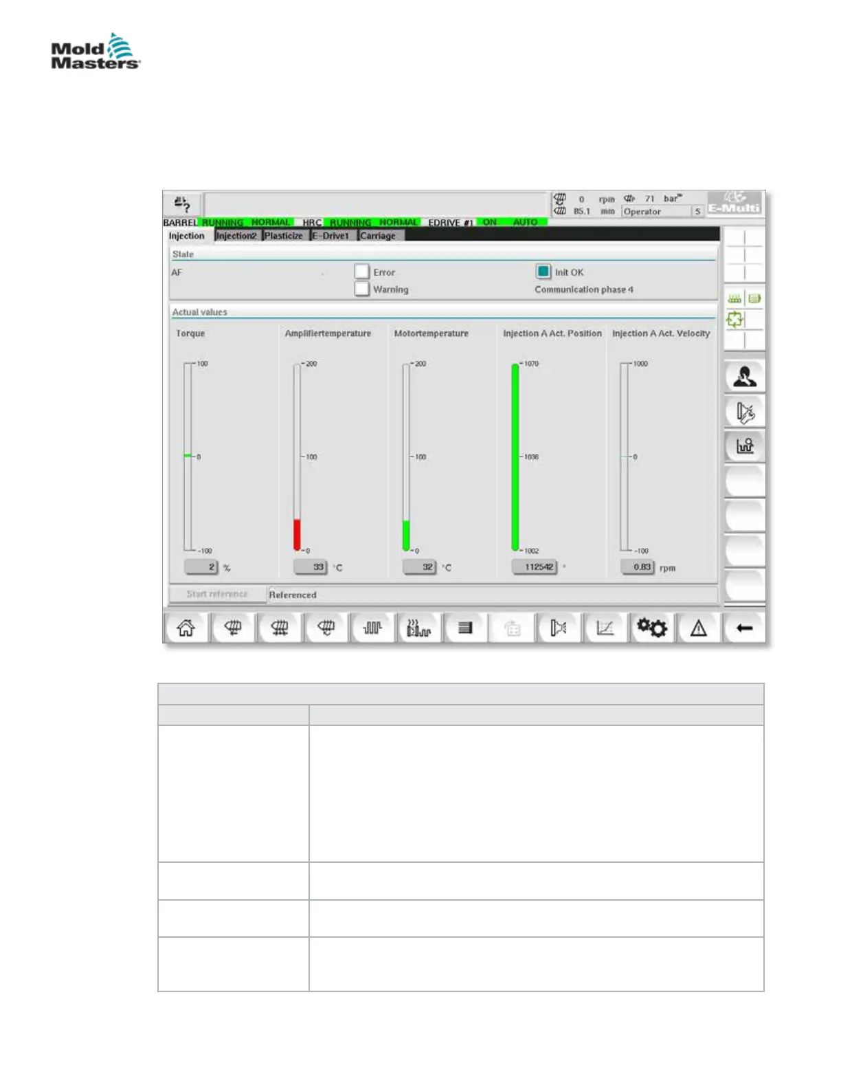
7.28 Drive Monitor Screen
This screen shows the drive parameters (actual values) during live operation.
The screen gives a simple overview of each drive in the system and helps
with making an initial diagnosis in case problems occur on a drive. The
screen shows information pertaining to the respective drive (Injection,
Injection2, Plasticize, Carriage). Each drive is shown on a separate tab.
Figure 7-33 Drive monitor screen
Table 7-47 Drive Manager Screen Components
Screen Components Description
State Shows the drive states. Possible drive states:
• AF = Drive enabled
• Ab = Drive ready but not enabled
• AH = Drive halt
• bb = Drive ready but no 400 / 480VAC supply voltage. Check drive
supply circuit breaker.
• STO = Drive safety circuit open, check E-Stop and Gate circuits.
• Fxxxx = Drive faulted (xxxx is the fault number)
Error Indicates if the drive has an active fault.
The fault is displayed in the alarm screen.
Warning Display of a pending warning message for this drive.
The warning message is displayed in the alarm screen.
Init OK Initialization status of the drive (display only)
• Green = Drive is initialized and ready for operation
• Empty = Drive is not initialized / ready for operation
7-74
© 2020 Mold-Masters (2007) Limited. All Rights Reserved.
E-MULTI CONTROLLER HMI INTERFACE
E-Multi Controller User Manual