Table 7-9 Injection Settings Screen Components
Screen Components Description
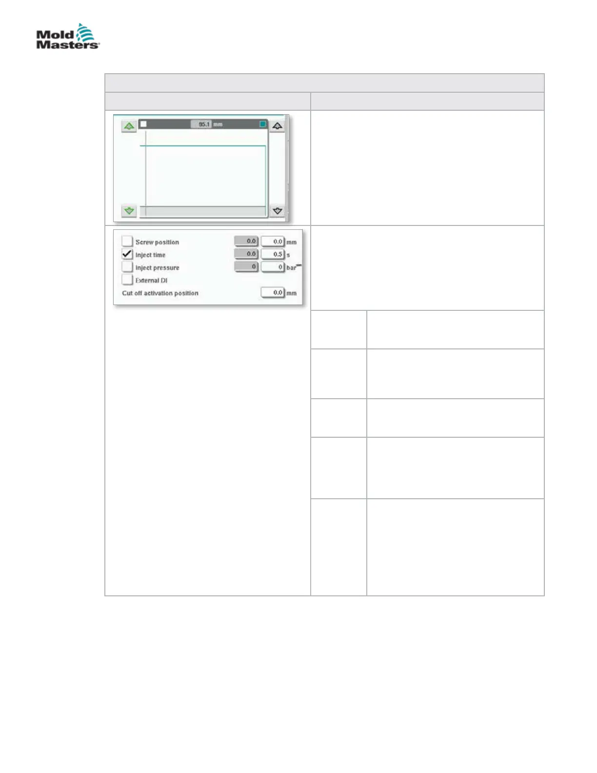
Pressure and Velocity Input Graph
Alternatively, the Pressure (teal) and the Velocity
(grey) values are shown in the form of prole graphs
and the values can be adjusted using the arrow
keys next to the prole graphs.
On each tap of the arrow, the prole graph is
adjusted by +/-5 bar and/or +/-5%.
Transition Conditions
Used to set the conditions when the system
changes from injection to the hold.
If multiple conditions are selected, the change will
occur when the rst condition is met.
Activate conditions by checking the box to the left of
the eld label.
Screw
position
Species the screw position at which
the system changes to hold pressure.
Inject time Species the number of seconds after
which the system changes to hold
pressure (measured from the start of
the injection process).
Inject
pressure
Species the injection pressure at
which the system changes to hold
pressure.
External
DI
The cut o position is signaled by an
external digital input. The digital input
is shown on the electrical schematics
and is labeled:
Hold Transition (External).
Cut O
Activation
Position
Injection pressure for transition will not
be monitored until the screw position
is less than this position. It is used
to prevent transition when injection
pressure spikes at the start of injection.
Note: This eld is only available when
transition on injection pressure is
selected.
Injection Settings Screen - continued
7-14
© 2020 Mold-Masters (2007) Limited. All Rights Reserved.
E-MULTI CONTROLLER HMI INTERFACE
E-Multi Controller User Manual