Table 7-13 Recovery Settings Screen Components
Screen Components Description
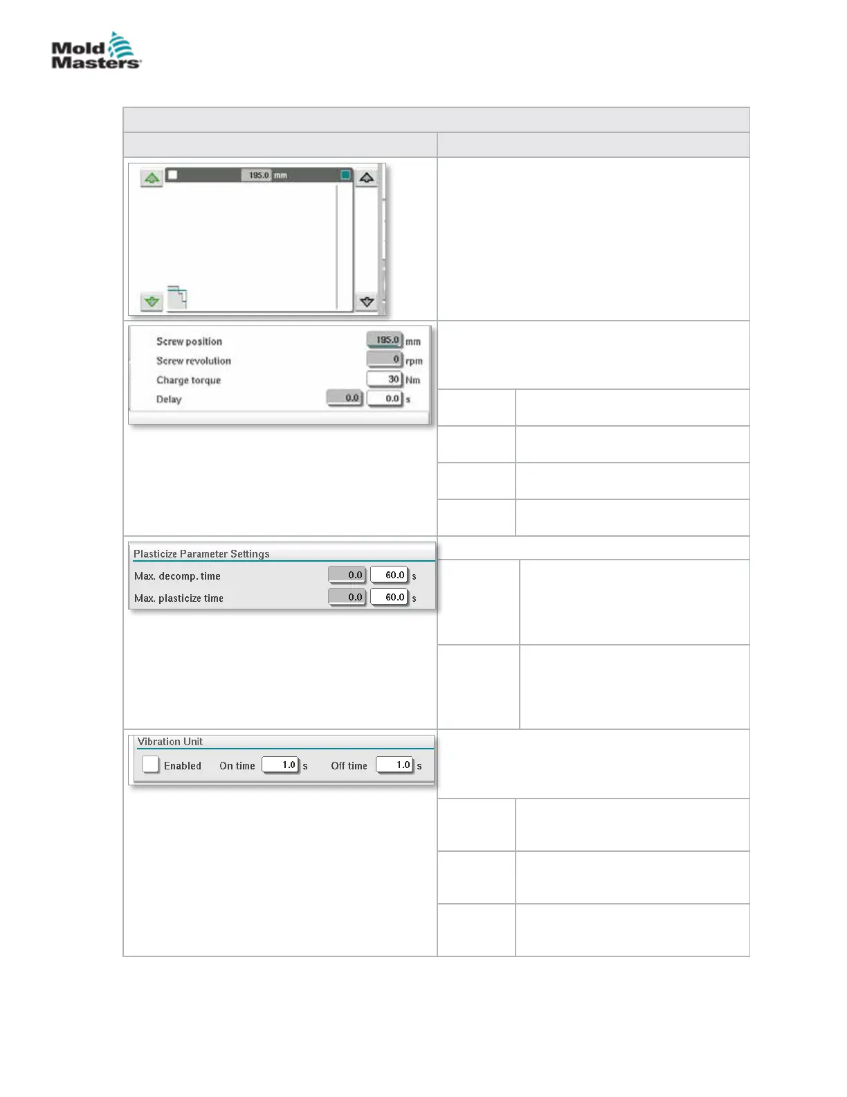
Backpressure and Charge Input Graph
Alternatively, the Backpressure (teal) and the
Charge (grey) values are shown in the form of
prole graphs and the values can be adjusted
using the arrow keys next to the prole graphs.
On each click of the arrow, the prole graph is
adjusted by +/-5 bar and/or +/-5%.
Data Display
This area of the screen displays the current inject
pressure and screw revolution and position.
The Delay eld can be adjusted - see below.
Screw
position
Displays the current screw position.
Screw
revolution
Displays the current screw revolution.
Charge
torque
Species the maximum charge
torque.
Delay The delay time for the start of
plasticize is specied here.
Plasticize Parameter Settings
Max.
decomp.
time
Here the maximum allowed
decompression time can be set.
This value is the maximum allowed
value to be input on the plasticize
screen.
Max.
plasticize
time
Here the maximum allowed
plasticize time can be set.
If the time is exceeded an alarm
will be raised and the cycle will be
stopped.
Vibration Unit
An optional vibrator may be attached to the hopper
or feed tube. Vibration can be used to help the
ow of material into the feed block.
Enabled Checking this box will enable the
vibration unit. Unchecking the box will
disable the vibration unit.
On Time Species the amount of time the
vibration is on within the on / o
cycle.
O Time Species the amount of time the
vibration is o within the on / o
cycle.
Recovery Settings Screen - continued
7-19
© 2020 Mold-Masters (2007) Limited. All Rights Reserved.
E-MULTI CONTROLLER HMI INTERFACE
E-Multi Controller User Manual