Chapter E: Basic repair procedures 2 Basic repair procedures
Technical manual Planmeca PlanMill 40 111
Because the replacement assembly may possibly be used in other mill configurations a
configuration note is included with the assembly. The following is a copy of the text
contained in a note included with each mounted accelerometer processor assembly FRU
kit.
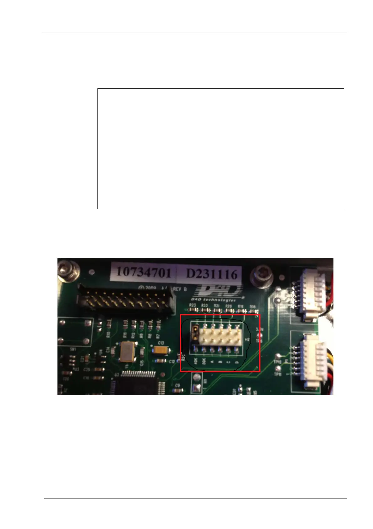
The following is a close up of the accelerometer processor board, which shows the location
of the jumper, installed in the position for a 40K (Config 1) milling unit.
Figure 95: Jumper location (PlanMill 40, Move to “A”)
Tools required
• #1 Philips screwdriver
• long nose needle nose pliers
• wire cutters
• cable ties
Table 24: Installer note
1 Regarding jumper on circuit board:
• Note that the jumper on this circuit board is normally predefined in the “40K”
position.
• If this circuit board is installed in a 50K Config 2 mill (serial number is older than
107001), move the jumper to the “50K” position.
• If this circuit board is installed in a 50K Config 3 (serial number is 107001 or bigger),
move the jumper to the “A” position.
2 Regarding cabling and sensor connection:
• The cable marked with P/N 10797901 connects to the tool break sensor board
mounted on the spindle motor on the right side of the mill and to the P1 connector
on the tool break processor board.
• The cable marked with P/N 10797902 connects to the tool break sensor board
mounted on the spindle motor on the left side of the mill and to the P4 connector on
the tool break processor board.