2 Basic repair procedures Chapter E: Basic repair procedures
112 Planmeca PlanMill 40 Technical manual
Removal
1. Remove top, rear and right side covers of the milling unit per procedures.
2. Power the milling unit down.
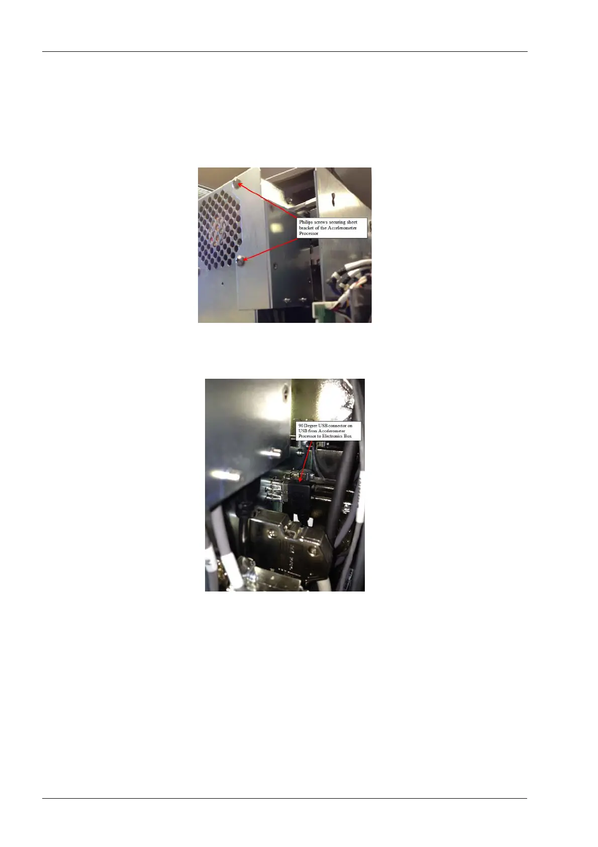
3. Using the #1 Philips screwdriver remove the 2 Philips screws securing the sheet
metal bracket to the rear of the electronics box.
Figure 96: Removing accelerometer processor assembly
4. Using long nose needle nose pliers carefully grasp and unplug the black 90 degree
USB connector from the back of the electronics box.
Figure 97: Disconnecting USB cable
5. Leave the PCBA and the cables attached to the sheet metal bracket.
The 2 grey cables attached to the accelerometer PCBA are routed through mill and
attached to 2 accelerometer sensors, which are mounted on the spindle motors.
6. Follow the instructions in section 2.2.7 "LCD touch display assembly" on page 109 to
unmount the LCD touch display in order to gain access to the accelerometer sensor
which is mounted on the right side spindle motor.
7. Use wire cutters to carefully the cable ties that help secure the 2 grey cables to the
accelerometer sensors.