2 Basic repair procedures Chapter E: Basic repair procedures
114 Planmeca PlanMill 40 Technical manual
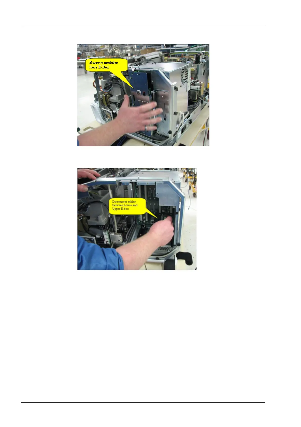
Figure 99: Remove modules from E-box
5. Disconnect cable assemblies between upper and lower E-box units.
Figure 100: Disconnect cable assemblies
6. Disconnect the +42 Vdc power cable (violet/black) from the backplane PCB assembly
in the upper electronics box assembly.
7. Detach the lug of the violet wire from “TB1” and the black wire from “TB2” at the lower
left-hand corner of the backplane PCB assembly by removing the PHCS 6-32x0.375
Phillips screws provided.
Secure these screws in a safe place. They will be used to reinstall the lower box to the
system.
8. Disconnect the 4-pin 115/230 Vac cable (black/white/white/black) from “P1” at the
lower right-hand corner of the backplane PCB assembly.