Chapter E: Basic repair procedures 2 Basic repair procedures
Technical manual Planmeca PlanMill 40 115
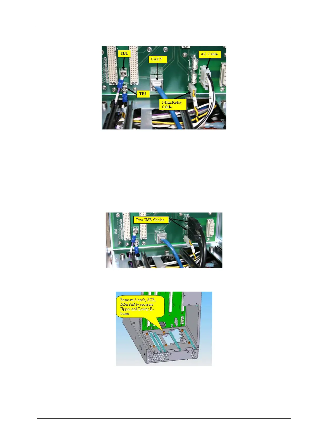
Figure 101: Disconnect cables
9. Disconnect the 2-pin power relay cable (yellow/black) from “J1” at the lower right-
hand corner of the backplane PCB assembly.
10. Disconnect the Ethernet CAT 5 cable from “J12” at the lower center of the backplane
PCB assembly.
11. Disconnect the two USB cables from “J10” and “J21” at the lower right-hand corner of
the backplane PCB assembly.
The USB cable connections are not USB port specific.
Figure 102: Remove screws from bottom of upper E-box
12. Remove (Qty 6) screws (M5x.8x8) from the bottom of upper E-box.
Figure 103: Remove screws from bottom of upper E-box
13. Remove (Qty 2) screws (M3x.5x8) from the lower Y-axis chain mount.