2 Basic repair procedures Chapter E: Basic repair procedures
116 Planmeca PlanMill 40 Technical manual
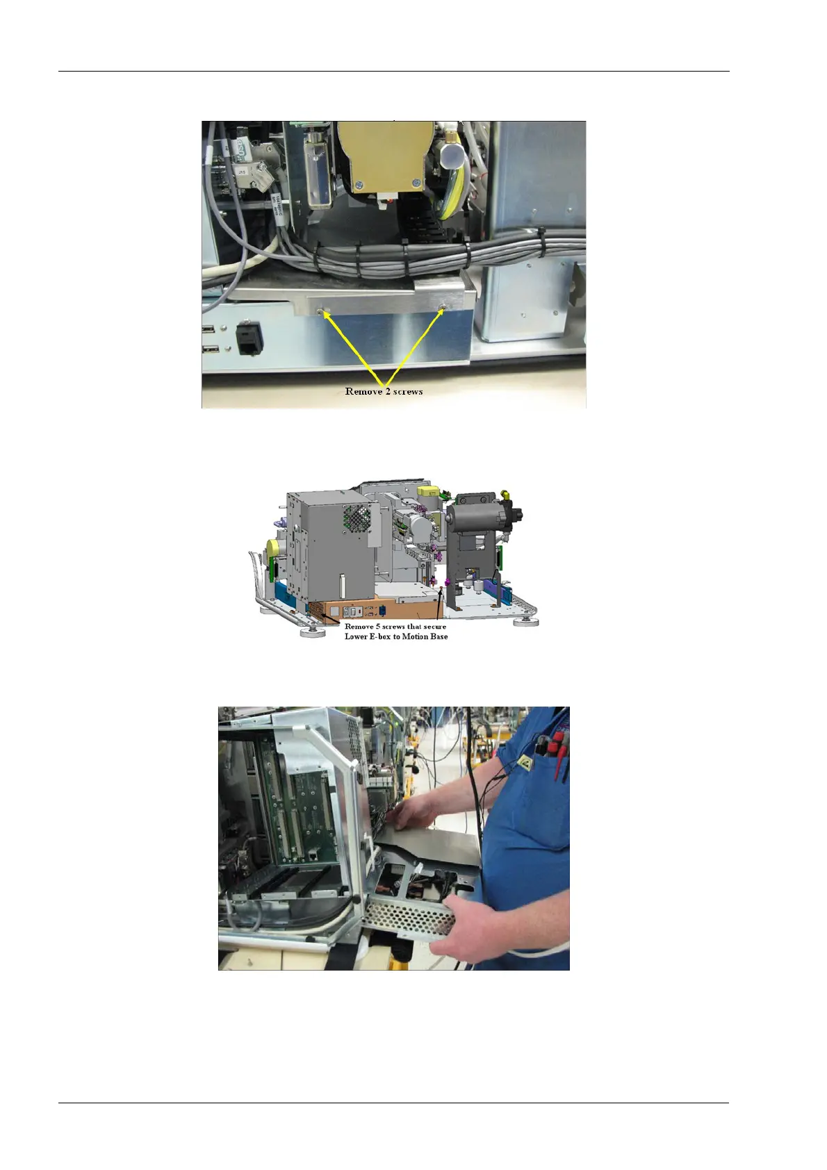
Figure 104: Remove screws from lower Y-axis chain mount
14. Remove (Qty 5) screws (M4x.7x8) from bottom of lower E-box.
Figure 105: Remove screws securing lower E-box to bottom plate
15. Carefully work lower E-box unit out from under the upper E-box unit.
Figure 106: Remove lower E-box
16. Install replacement lower E-box by reversing the above procedure.