Chapter D: Troubleshooting 2 Troubleshooting
Technical manual Planmeca PlanMill 40 91
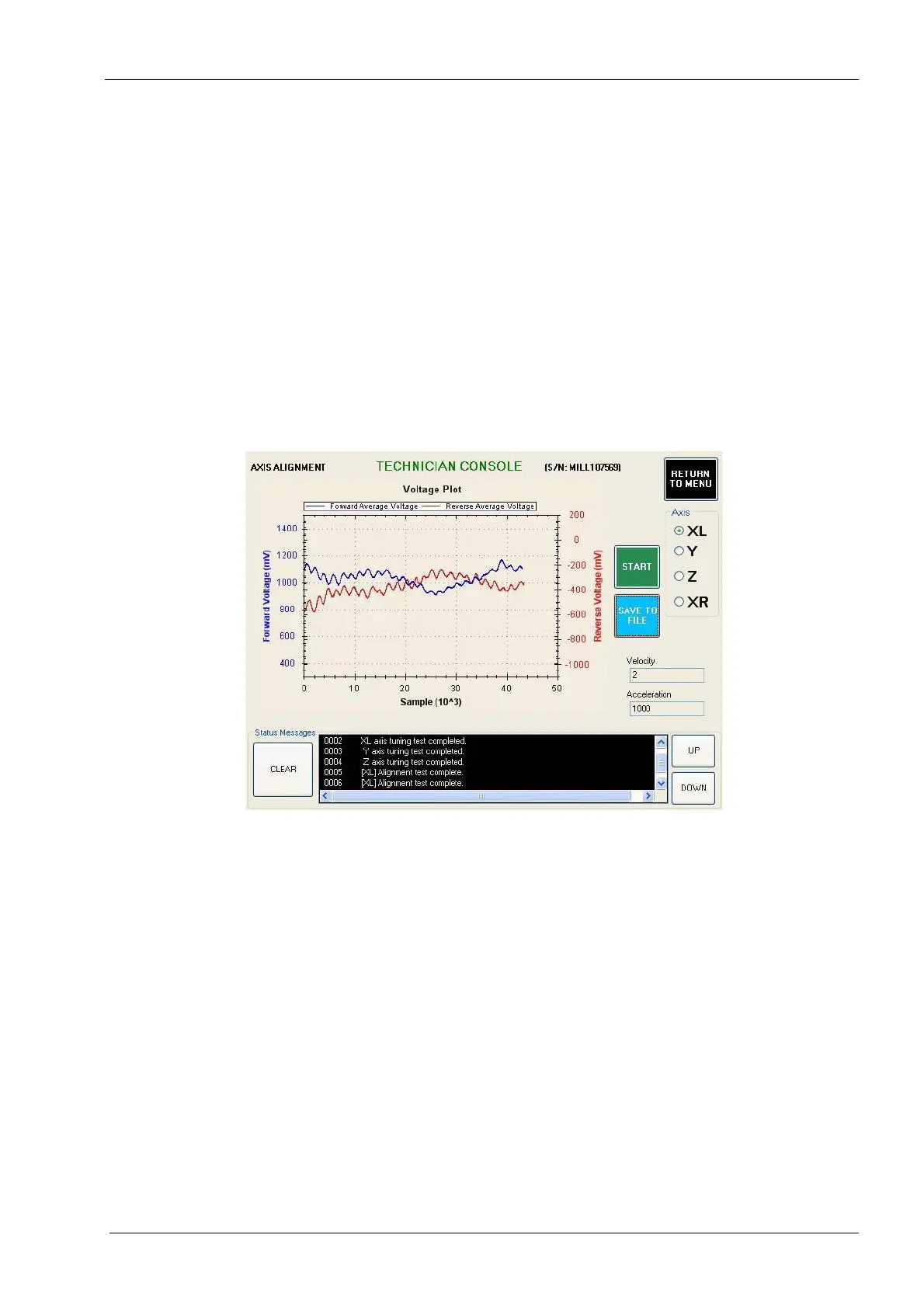
9. Navigate to: Technician Console -> Motion Diagnostics -> Axis Alignment.
10. Select the axis to test and then select the Start button. Evaluate the graph using
guidelines shown below. Two main characteristics to look for in the axis alignment
graph are:
• Both the forward and reverse graphs (blue and red respectively) should be close
to horizontal. A graph that has a steep upwards or downwards slope is an
indication of an axis assembly that is out of alignment and may need to be
repaired for optimal performance.
• Neither graph should exceed 4volts (4000mV). A graph that exceeds 4volts is an
indication of an axis assembly that is out of alignment and may need to be
repaired for optimal performance.
Dry and/or old spindle housing rope packing on the XL and/or XR axis can affect the results
of the axis alignment test.
Figure 70: Example of GOOD axis alignment graph
11. If the axis alignment graph is good but that axis failed the servo diagnostics test, then
replace the servo motor and/or cable and repeat the servo diagnostics test. If the axis
alignment graph is bad, realign the axis assembly and retest.
12. In the event all four axes have passed all the tests described so far and an issue with
the function of the mill still exists, it is probable that the problem is intermittent and
therefore will be difficult to diagnose. Following is a list of components that when
defective can cause the motion system to fail. Consider each of these components
when further troubleshooting a motion system issue.
• lid interlock switches/cable
• home/end limit sensors and/or cables
• CPU module (motion controller, interface PCB, hard drive)
• lower E-box (48 volt power supply)
• power module
• Amp module
• E-box backplane PCB
• servo motor/cable